
APPENDIX
App. - 23
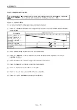
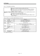
(7) Perform all risk assessments and safety level certification to the machine or the system as a whole.
It is recommended that a Certification Body final safety certification of the system be used.
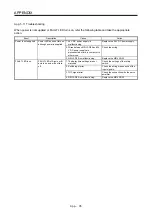
(8) To prevent accumulation of multiple malfunctions, perform a malfunction check at regular intervals as
deemed necessary by the applicable safety standard. Regardless of the system safety level, malfunction
checks should be performed at least once per year.
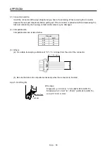
(9) If the upper and lower power module in the servo amplifier are shorted and damaged simultaneously, the
servo motor may make a half revolution at a maximum.
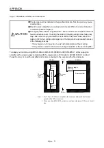
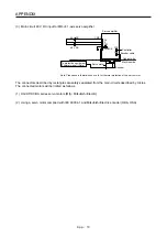
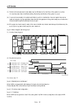
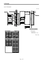
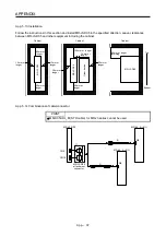
App. 5.5 Block diagram and timing chart
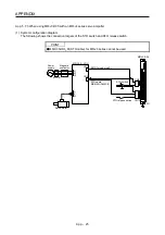
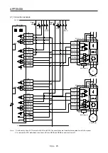
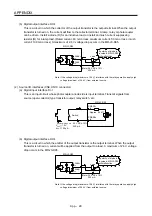
(1) Function block diagram
SDI1A-
SDI2A-
SDI1B-
SDI2B-
STO1A- STO2A-
SDO1A- SDO2A-
SRESA+ SRESA-
TOF1A
TOF2A
STO1A+ STO2A+
SDO1A+ SDO2A+
TOFA
0V
+24V
DCDC
power
Safety logic
TIMER1
TIMER2
A-axis circuit
SW1 SW2
B-axis circuit
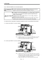
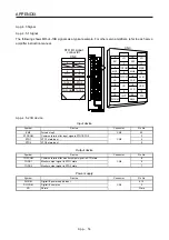
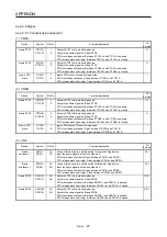
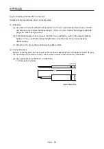
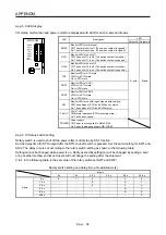
(2) Operation sequence
A-axis shutdown 1 and 2
B-axis shutdown 1 and 2
Energizing (close)
Shut-off (open)
Release (close)
Normal (open)
Normal (close)
Shut-off (open)
A-axis EMG start/reset
B-axis EMG start/reset
A-axis STO state 1 and 2
B-axis STO state 1 and 2
10 ms or shorter
Shut off delay (SW1 and SW2) (Note)
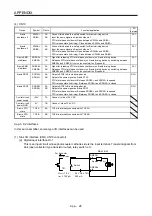
STO status
Control enabled
STO status
50 ms or longer
SDI
SRES
STO
15 ms or longer
Power supply
Control enabled
Note. Refer to App. 5.10.
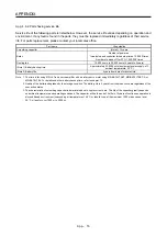
App. 5.6 Maintenance and disposal
MR-J3-D05 is equipped with LED displays to check errors for maintenance.
Please dispose this unit according to your local laws and regulations.
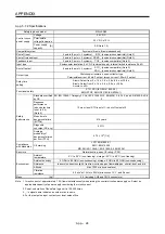
App. 5.7 Functions and configuration
App. 5.7.1 Summary
MR-J3-D05 has two systems in which the each system has SS1 function (delay time) and output of STO
function.
Summary of Contents for MR-J4-100A(-RJ)
Page 19: ...10 MEMO ...
Page 75: ...1 FUNCTIONS AND CONFIGURATION 1 56 MEMO ...
Page 83: ...2 INSTALLATION 2 8 MEMO ...
Page 159: ...3 SIGNALS AND WIRING 3 76 MEMO ...
Page 203: ...4 STARTUP 4 44 MEMO ...
Page 351: ...7 SPECIAL ADJUSTMENT FUNCTIONS 7 40 MEMO ...
Page 365: ...8 TROUBLESHOOTING 8 14 MEMO ...
Page 387: ...9 DIMENSIONS 9 22 MEMO ...
Page 403: ...10 CHARACTERISTICS 10 16 MEMO ...
Page 553: ...12 ABSOLUTE POSITION DETECTION SYSTEM 12 30 MEMO ...
Page 567: ...13 USING STO FUNCTION 13 14 MEMO ...
Page 607: ...14 COMMUNICATION FUNCTION MITSUBISHI ELECTRIC GENERAL PURPOSE AC SERVO PROTOCOL 14 40 MEMO ...
Page 639: ...15 USING A LINEAR SERVO MOTOR 15 32 MEMO ...
Page 767: ...18 MR J4 03A6 RJ SERVO AMPLIFIER 18 84 MEMO ...
Page 856: ...APPENDIX App 41 ...
Page 905: ...MEMO ...


