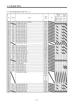
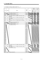
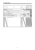
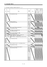


5. PARAMETERS
5 - 21
No./symbol/
name
Setting
digit
Function
Initial
value
[unit]
Control
mode
P S T
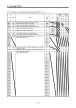
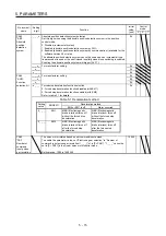
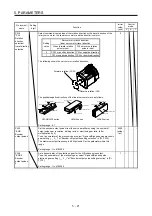
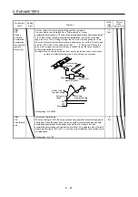
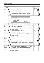
PA14
*POL
Rotation
direction
selection/
travel direction
selection
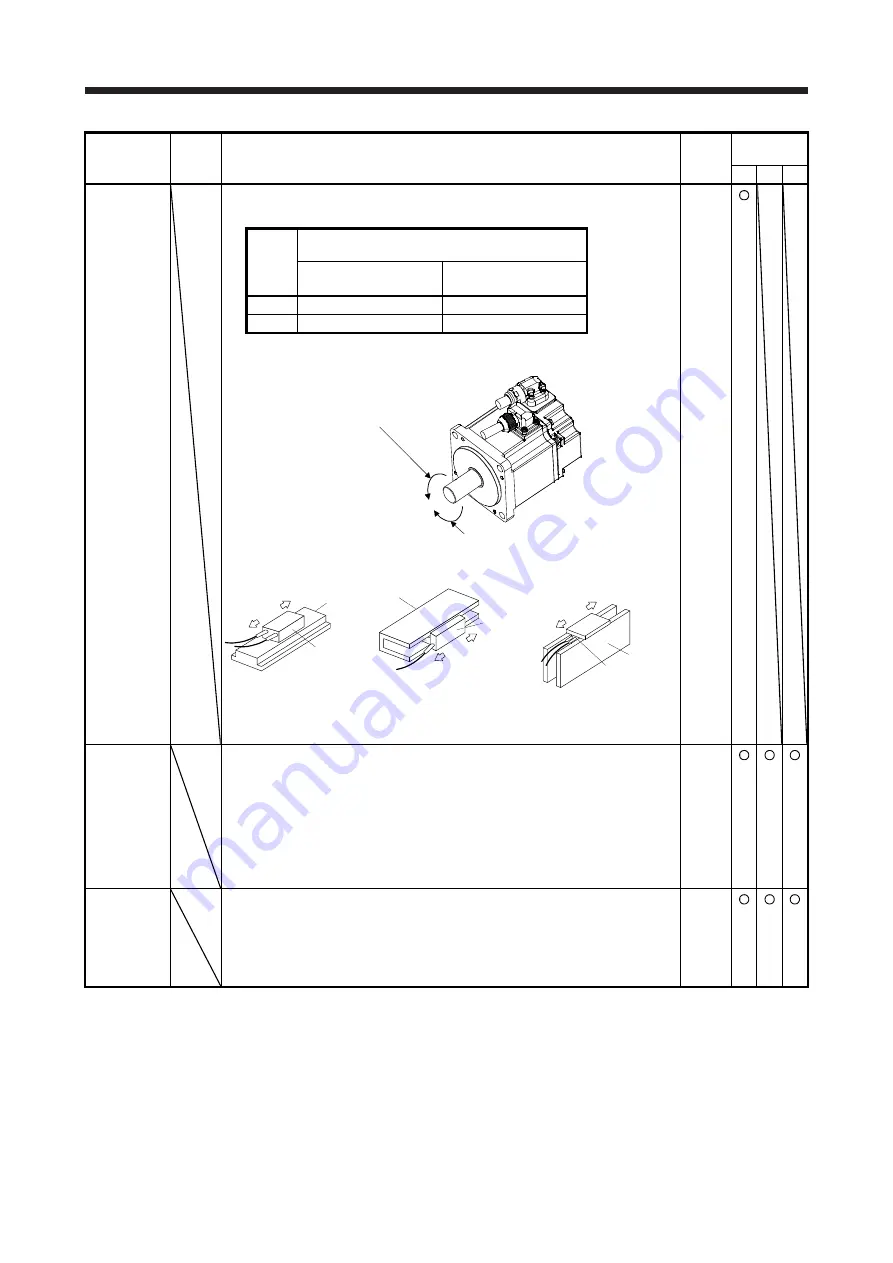
Select command input pulses of the rotation direction or the travel direction of the
rotary servo motor, the linear servo motor and the direct drive motor.
0
Setting
value
Servo motor rotation direction/
linear servo motor travel direction
When forward rotation
pulse is input
When reverse rotation
pulse is input
0
CCW or positive direction CW or negative direction
1
CW or negative direction CCW or positive direction
The following shows the servo motor rotation directions.
Forward rotation (CCW)
Reverse rotation (CW)
The positive/negative directions of the linear servo motor are as follows.
Secondary side
Primary side
Positive direction
Negative direction
LM-H3/LM-F series
Negative direction
Positive direction
Secondary side
Primary side
LM-U2 series
Negative direction
Positive direction
Table
Primary side
Secondary side
LM-K2 series
Setting range: 0, 1
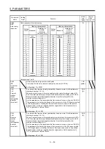
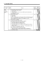
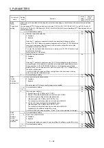
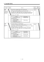
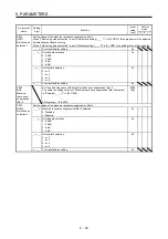
PA15
*ENR
Encoder
output pulses
Set the encoder output pulses from the servo amplifier by using the number of
output pulses per revolution, dividing ratio, or electronic gear ratio. (after
multiplication by 4)
To set a numerator of the electronic gear, select "A-phase/B-phase pulse electronic
gear setting (_ _ 3 _)" of "Encoder output pulse setting selection" in [Pr. PC19].
The maximum output frequency is 4.6 Mpulses/s. Set the parameter within this
range.
Setting range: 1 to 4194304
4000
[pulse/
rev]
PA16
*ENR2
Encoder
output pulses
2
Set a denominator of the electronic gear for the A/B-phase pulse output.
To set a denominator of the electronic gear, select "A-phase/B-phase pulse
electronic gear setting (_ _ 3 _)" of "Encoder output pulse setting selection" in [Pr.
PC19].
Setting range: 1 to 4194304
1
Summary of Contents for MR-J4-100A(-RJ)
Page 19: ...10 MEMO ...
Page 75: ...1 FUNCTIONS AND CONFIGURATION 1 56 MEMO ...
Page 83: ...2 INSTALLATION 2 8 MEMO ...
Page 159: ...3 SIGNALS AND WIRING 3 76 MEMO ...
Page 203: ...4 STARTUP 4 44 MEMO ...
Page 351: ...7 SPECIAL ADJUSTMENT FUNCTIONS 7 40 MEMO ...
Page 365: ...8 TROUBLESHOOTING 8 14 MEMO ...
Page 387: ...9 DIMENSIONS 9 22 MEMO ...
Page 403: ...10 CHARACTERISTICS 10 16 MEMO ...
Page 553: ...12 ABSOLUTE POSITION DETECTION SYSTEM 12 30 MEMO ...
Page 567: ...13 USING STO FUNCTION 13 14 MEMO ...
Page 607: ...14 COMMUNICATION FUNCTION MITSUBISHI ELECTRIC GENERAL PURPOSE AC SERVO PROTOCOL 14 40 MEMO ...
Page 639: ...15 USING A LINEAR SERVO MOTOR 15 32 MEMO ...
Page 767: ...18 MR J4 03A6 RJ SERVO AMPLIFIER 18 84 MEMO ...
Page 856: ...APPENDIX App 41 ...
Page 905: ...MEMO ...


