

11. OPTIONS AND PERIPHERAL EQUIPMENT
11 - 95
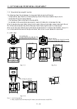
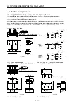
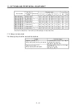
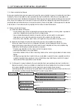
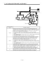
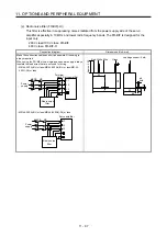
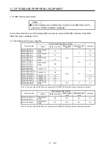
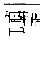
(c) Cable clamp fitting AERSBAN-_SET
Generally, connecting the grounding of the shielded wire to the SD terminal of the connector
provides a sufficient effect. However, the effect can be increased when the shielded wire is
connected directly to the grounding plate as shown below.
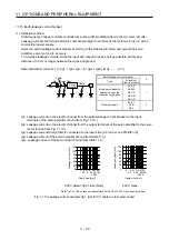
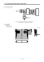
Install the grounding plate near the servo amplifier for the encoder cable. Peel part of the cable
sheath to expose the external conductor, and press that part against the grounding plate with the
cable clamp. If the cable is thin, clamp several cables in a bunch.
The clamp comes as a set with the grounding plate.
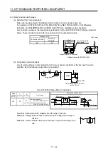
[Unit: mm]
Cable clamp
(A, B)
Cable
Earth plate
External conductor
Clamp section diagram
40
Strip the cable sheath of
the clamped area.
cutter
cable
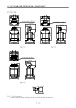
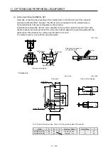
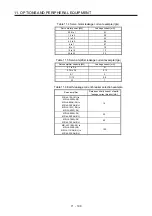
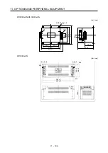
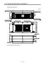
Dimensions
[Unit: mm]
Earth plate
(Note) M4 screw
11
3
6
C
A
6
22
17.5
35
35
7
24
0 -0.
2
B ± 0.3
2-
φ
5 hole
installation hole
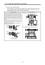
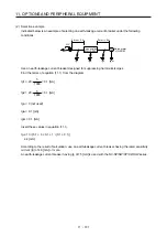
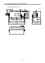
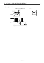
[Unit: mm]
Clamp section diagram
L or less
10
30
24
+ 0.
3
0
Note. Screw hole for grounding. Connect it to the grounding plate of the cabinet.
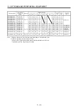
Model A
B
C
Accessory
fittings Clamp
fitting L
AERSBAN-DSET
100
86
30
Clamp A: 2 pcs.
A
70
AERSBAN-ESET
70
56
Clamp B: 1 pc.
B
45
Summary of Contents for MR-J4-100A(-RJ)
Page 19: ...10 MEMO ...
Page 75: ...1 FUNCTIONS AND CONFIGURATION 1 56 MEMO ...
Page 83: ...2 INSTALLATION 2 8 MEMO ...
Page 159: ...3 SIGNALS AND WIRING 3 76 MEMO ...
Page 203: ...4 STARTUP 4 44 MEMO ...
Page 351: ...7 SPECIAL ADJUSTMENT FUNCTIONS 7 40 MEMO ...
Page 365: ...8 TROUBLESHOOTING 8 14 MEMO ...
Page 387: ...9 DIMENSIONS 9 22 MEMO ...
Page 403: ...10 CHARACTERISTICS 10 16 MEMO ...
Page 553: ...12 ABSOLUTE POSITION DETECTION SYSTEM 12 30 MEMO ...
Page 567: ...13 USING STO FUNCTION 13 14 MEMO ...
Page 607: ...14 COMMUNICATION FUNCTION MITSUBISHI ELECTRIC GENERAL PURPOSE AC SERVO PROTOCOL 14 40 MEMO ...
Page 639: ...15 USING A LINEAR SERVO MOTOR 15 32 MEMO ...
Page 767: ...18 MR J4 03A6 RJ SERVO AMPLIFIER 18 84 MEMO ...
Page 856: ...APPENDIX App 41 ...
Page 905: ...MEMO ...


