


496
11.3.4
Creating a program to enable/disable the inching operation
A program must be created to execute an inching operation. Consider the "required control data setting", "start
conditions", and "start time chart" when creating the program.
The following shows an example when an inching operation is started for axis 1. (The example shows the inching
operation when a "10.0
m" is set in "[Cd.16] Inching movement amount".)
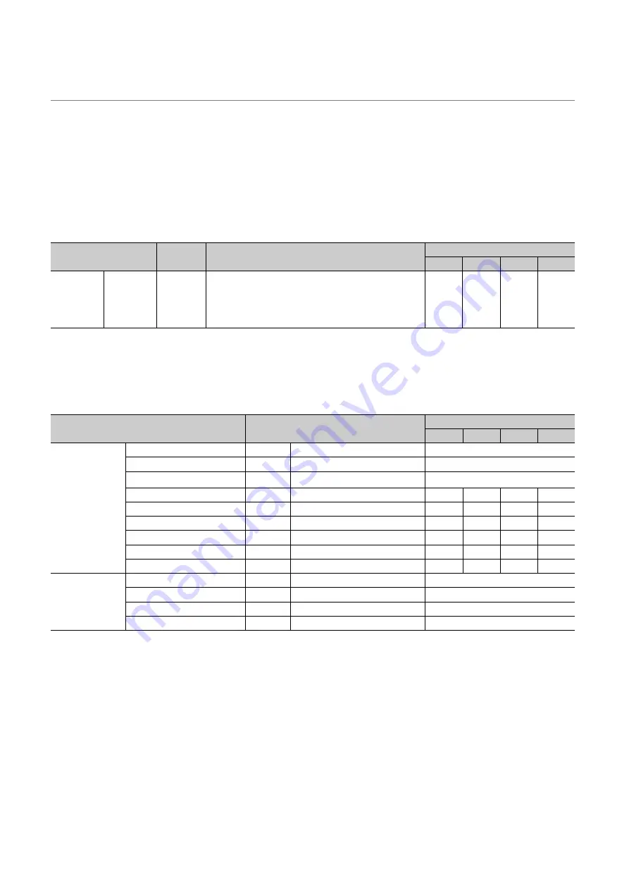
(1) Required control data setting
The control data shown below must be set to execute an inching operation. The setting is carried out with the
program.
Refer to
Page 211, Section 5.7 for the information on detail settings.
(2) Start conditions
The following conditions must be fulfilled when starting. The required conditions must also be assembled in the
program, and the program must be configured so the operation will not start if the conditions are not fulfilled.
*1
If the CPU module is set to the asynchronous mode in the synchronization setting, this must be inserted in the program
for interlocking. If it is set to the synchronous mode, it must not be inserted in the program for interlocking because it is
turned ON when the CPU module executes calculation.
Setting item
Setting
value
Setting details
Buffer memory address
Axis 1
Axis 2
Axis 3
Axis 4
[Cd.16]
Inching
movement
amount
100
Set the setting value so that the command pulse is not increased
larger than the maximum output pulse.
(The max. output pulse
LD75D
: 4Mpulse/s
LD75P
: 200kpulse/s)
1517
1617
1717
1817
Signal name
Signal state
Device
Axis 1
Axis 2
Axis 3
Axis 4
Interface signal
PLC READY signal
ON
CPU module preparation completed
Y0
LD75 READY signal
ON
LD75 preparation completed
X0
Synchronization flag
ON
LD75 buffer memory accessible
X1
Axis stop signal
OFF
Axis stop signal is OFF.
Y4
Y5
Y6
Y7
Start complete signal
OFF
Start complete signal is OFF.
X10
X11
X12
X13
BUSY signal
OFF
LD75 is not operating
XC
XD
XE
XF
Positioning complete signal
OFF
Positioning complete signal is OFF
X14
X15
X16
X17
Error detection signal
OFF
There is no error
X8
X9
XA
XB
M code ON signal
OFF
M code ON signal is OFF.
X4
X5
X6
X7
External signal
Drive unit READY signal
ON
Drive unit preparation completed
Stop signal
OFF
Stop signal is OFF.
Upper limit (FLS)
ON
Within limit range
Lower limit (RLS)
ON
Within limit range
Summary of Contents for MELSEC-L LD75D
Page 2: ......
Page 11: ...9 Memo ...
Page 176: ...174 ...
Page 264: ...262 ...
Page 266: ...264 ...
Page 267: ...265 CHAPTER 6 PROGRAM USED FOR POSITIONING CONTROL 6 6 4 Positioning Program Examples ...
Page 268: ...266 ...
Page 269: ...267 CHAPTER 6 PROGRAM USED FOR POSITIONING CONTROL 6 6 4 Positioning Program Examples ...
Page 270: ...268 ...
Page 271: ...269 CHAPTER 6 PROGRAM USED FOR POSITIONING CONTROL 6 6 4 Positioning Program Examples ...
Page 272: ...270 Z ABRST1 instruction execution ...
Page 273: ...271 CHAPTER 6 PROGRAM USED FOR POSITIONING CONTROL 6 6 4 Positioning Program Examples ...
Page 278: ...276 ...
Page 279: ...277 CHAPTER 6 PROGRAM USED FOR POSITIONING CONTROL 6 6 4 Positioning Program Examples ...
Page 280: ...278 ...
Page 281: ...279 CHAPTER 6 PROGRAM USED FOR POSITIONING CONTROL 6 6 4 Positioning Program Examples ...
Page 282: ...280 ...
Page 283: ...281 CHAPTER 6 PROGRAM USED FOR POSITIONING CONTROL 6 6 4 Positioning Program Examples ...
Page 284: ...282 ...
Page 285: ...283 CHAPTER 6 PROGRAM USED FOR POSITIONING CONTROL 6 6 4 Positioning Program Examples ...
Page 286: ...284 ...
Page 287: ...285 CHAPTER 6 PROGRAM USED FOR POSITIONING CONTROL 6 6 4 Positioning Program Examples ...
Page 316: ...314 Memo ...
Page 685: ...683 APPENDICES A Appendix 1 Function Update Appendix 1 1 Function comparison Memo ...
Page 738: ...736 Memo ...
Page 817: ......


