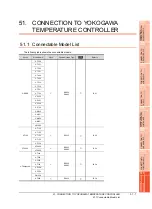
51. CONNECTION TO YOKOGAWA TEMPERATURE CONTROLLER
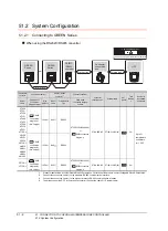
51.3 Connection diagram
51 - 9
44
CO
NNECTIO
N T
O
PAN
ASONIC
IND
U
STRIAL
DEV
IC
ES SUNX PLC
45
CONNECTION T
O
HIT
A
CHI IES
PL
C
46
CONNECTION T
O
HIT
A
CHI P
L
C
47
CONNE
C
T
ION T
O
FUJI
P
L
C
48
CO
NN
EC
TI
O
N T
O
FU
JI
T
E
M
P
E
R
A
T
UR
E
CO
NT
RO
LL
E
R
49
CONNECTION
T
O
Y
A
SKA
W
A
PL
C
50
C
O
NNECTION T
O
YOK
OGA
W
A
PL
C
51
CON
NECT
IO
N T
O
YO
KO
G
AW
A T
EMP
ERA
TUR
E
CON
TROLLE
R
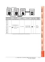
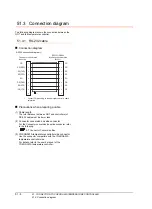
51.3.2 RS-485 cable
Connection diagram
RS485 connection diagram 1)
*1
Pin No. of temperature controller differs depending on the model.Refer to the following table.
*2
Terminating resistor should be provided for a temperature controller which will be a terminal.
*3
Turn on the terminating switch on the RS232C/RS485 converter at the end.
*4
Connect FG grounding to the appropriate part of a cable shield line.
*5
When the suffix code is "1" in type 3 except "1" or "6" in type 2
*6
When the suffix code is "1" or "2" in type 2 without the optional suffix code "/LP"
*7
(For standard) when the suffix code is "1" in type 3 except "3" in type 2, (for detail) when the optional suffix code is "/CH3"
*8
(For standard) when the suffix code is "2" in type 2, (for detail) when the optional suffix code is "/CH4"
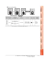
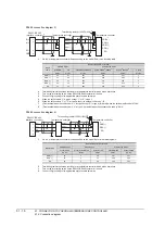
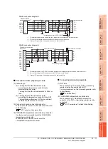
RS485 connection diagram 2)
*1
Pin No. of temperature controller differs depending on the model. Refer to the following table.
*2
Terminating resistor (100
1/2W) should be provided for a temperature controller which will be a terminal.
*3
Set the terminating resistor setting switch of the GOT main unit to "Enable".
*4
Connect FG grounding to the appropriate part of a cable shield line.
*5
When the suffix code is "1" in type 3 except "1" or "6" in type 2
*6
When the suffix code is "1" or "2" in type 2 without the optional suffix code "/LP"
*7
(For standard) when the suffix code is "1" in type 3 except "3" in type 2, (for detail) when the optional suffix code is "/CH3"
*8
(For standard) when the suffix code is "2" in type 2, (for detail) when the optional suffix code is "/CH4"
Temperature
controller
RS232C/RS485
interface converter
*3
RDA(-)
RDB(+)
SDA(-)
SDB(+)
SG
1
2
3
4
5
6
RDA(-)
RDB(+)
SDA(-)
SDB(+)
SG
SDA(-)
SDB(+)
RDA(-)
RDB(+)
SG
GND
Temperature controller
Terminating resistor(220
Ω
1/4W)
*2
*4
*4
*1
*1
Signal
name
Model of temperature controller
GREEN Series
UTAdvanced Series
UT/UP/UM
US
UT32A/UP35A/UM33A
UT35A/UT55A
*5
/UP55A
*7
UT55A
*6
/UP55A
*8
UT75A
Pin No.
Pin No.
Pin No.
Pin No.
Pin No.
Pin No.
RDA (-)
26
24
305
411
505
5
RDB (+)
25
23
304
410
504
4
SDB (+)
23
21
301
407
501
1
SDA (-)
24
22
302
408
502
2
SG
27
25
303
409
503
3
SDB(+)
SDA(-)
RDB(+)
RDA(-)
SG
2
7
1
6
5
3
4
8
9
-
SDB(+)
SDA(-)
RDB(+)
RDA(-)
SG
RDA
RDB
SDA
SDB
SG
RSA
CSA
RSB
CSB
FG
*4
*4
*1
*1
Connector conversion
box
side
*3
Temperature
controller
Temperature
controller
Terminating resistor
*2
Signal
name
Model of temperature controller
GREEN Series
UTAdvanced Series
UT/UP/UM
US
UT32A/UP35A/UM33A
UT35A/UT55A
*5
/UP55A
*7
UT55A
*6
/UP55A
*8
UT75A
Pin No.
Pin No.
Pin No.
Pin No.
Pin No.
Pin No.
SDB (+)
23
21
301
407
501
1
SDA (-)
24
22
302
408
502
2
RDB (+)
25
23
304
410
504
4
RDA (-)
26
24
305
411
505
5
SG
27
25
303
409
503
3
Summary of Contents for GT16
Page 1: ......
Page 2: ......
Page 46: ...1 4 1 OVERVIEW 1 1 Features ...
Page 54: ...2 8 2 SYSTEM CONFIGURATION 2 2 System Equipment ...
Page 60: ...3 6 3 SPECIFICATIONS 3 4 Battery specifications ...
Page 72: ...5 8 5 UL cUL STANDARDS AND EMC DIRECTIVE 5 2 EMC Directive ...
Page 102: ...6 30 6 OPTION 6 7 Connector Conversion Box ...
Page 106: ...7 4 7 INSTALLATION 7 1 Installing Procedure ...
Page 110: ...8 4 8 COMMUNICATION CABLE 8 1 Overview of Communication Cable ...
Page 130: ...9 20 9 HANDLING OF POWER WIRING AND SWITCH 9 4 Switch Wiring ...
Page 142: ...10 12 10 UTILITY FUNCTION 10 3 Utility Display ...
Page 184: ...11 42 11 DISPLAY AND OPERATION SETTINGS GOT SET UP 11 4 Maintenance Function ...
Page 202: ...12 18 12 COMMUNICATION INTERFACE SETTING COMMUNICATION SETTING 12 3 Ethernet Setting ...
Page 226: ...13 24 13 DEBUG 13 3 Memory Data Control ...
Page 248: ...14 22 14 SELF CHECK 14 2 Batch Self Check ...
Page 350: ...15 102 15 DATA CONTROL 15 3 OS Project Information ...
Page 410: ...19 22 19 TROUBLESHOOTING 19 2 Error Message and System Alarm ...
Page 418: ...App 8 APPENDICES Appendix 3 Transportation Precautions ...
Page 422: ...REVISIONS 4 ...
Page 425: ......
Page 426: ......
Page 427: ......
Page 428: ......
Page 470: ......
Page 510: ...21 22 21 COMPUTER LINK CONNECTION 21 6 Precautions ...
Page 568: ...22 58 22 ETHERNET CONNECTION 22 5 Precautions ...
Page 584: ......
Page 626: ...25 14 25 SERVO AMPLIFIER CONNECTION 25 7 Precautions ...
Page 632: ...26 6 26 ROBOT CONTROLLER CONNECTION 26 6 Precautions ...
Page 647: ...MULTIPLE GOT CONNECTIONS 29 GOT MULTI DROP CONNECTION 29 1 ...
Page 648: ......
Page 659: ...MULTI CHANNEL FUNCTION 30 MULTI CHANNEL FUNCTION 30 1 ...
Page 660: ......
Page 675: ...FA TRANSPARENT FUNCTION 31 FA TRANSPARENT FUNCTION 31 1 ...
Page 676: ......
Page 742: ...31 66 31 FA TRANSPARENT FUNCTION 31 7 Precautions ...
Page 744: ......
Page 766: ...32 22 32 CONNECTION TO IAI ROBOT CONTROLLER 32 7 Precautions ...
Page 802: ...34 10 34 CONNECTION TO OMRON TEMPERATURE CONTROLLER 34 7 Precautions ...
Page 834: ...36 18 36 CONNECTION TO KOYO EI PLC 36 6 Device Range that Can Be Set ...
Page 858: ...38 12 38 CONNECTION TO SHARP PLC 38 6 Device Range that Can Be Set ...
Page 868: ...39 10 39 CONNECTION TO SHINKO TECHNOS INDICATING CONTROLLER 39 7 Precautions ...
Page 902: ...42 6 42 CONNECTION TO TOSHIBA MACHINE PLC 42 6 Device Range that Can Be Set ...
Page 908: ...43 6 43 CONNECTION TO PANASONIC SERVO AMPLIFIER 43 7 Precautions ...
Page 970: ...48 12 48 CONNECTION TO FUJI TEMPERATURE CONTROLLER 48 7 Precautions ...
Page 1052: ...52 26 52 CONNECTION TO AZBIL CONTROL EQUIPMENT 52 7 Precautions ...
Page 1102: ...55 14 55 CONNECTION TO GE PLC 55 7 Precautions ...
Page 1114: ...57 4 57 CONNECTION TO SICK SAFETY CONTROLLER 57 5 Device Range that Can Be Set ...
Page 1128: ...59 2 59 CONNECTION TO HIRATA CORPORATION HNC CONTROLLER ...
Page 1130: ...60 2 60 CONNECTION TO MURATEC CONTROLLER ...
Page 1132: ......
Page 1270: ...62 68 62 MICROCOMPUTER CONNECTION ETHERNET 62 8 Precautions ...
Page 1271: ...MODBUS CONNECTIONS 63 MODBUS R RTU CONNECTION 63 1 64 MODBUS R TCP CONNECTION 64 1 ...
Page 1272: ......
Page 1292: ...64 12 64 MODBUS R TCP CONNECTION 64 7 Precautions ...
Page 1293: ...CONNECTIONS TO PERIPHERAL EQUIPMENT 65 VNC R SERVER CONNECTION 65 1 ...
Page 1294: ......
Page 1298: ...65 4 65 VNC R SERVER CONNECTION 65 4 Setting in Personal Computer ...
Page 1302: ...REVISIONS 4 ...
Page 1305: ......
Page 1306: ......


