


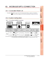


63. MODBUS(R)/RTU CONNECTION
63.5 MODBUS/RTU Equipment Side Setting
63 - 7
60
CONNECTION T
O
MURA
T
E
C
CONTROLL
ER
61
MI
C
R
O
C
OMPUTER
CONNECTION
(SE
R
IA
L)
62
MICR
OCOMPUTER
CONNECTION
(E
T
HE
RN
E
T)
63
MO
D
B
US(R)/
R
T
U
CONNE
C
T
ION
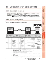
64
MO
DBUS(R)/
TCP
CON
N
E
C
T
ION
65
V
NC(R) S
E
R
V
E
R
CONNECTION
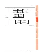
(b) When configuring individual communication
settings for specific channel numbers
The table below shows the settings for the GS
device.
63.5.2 Station number setting
In the MODBUS network, a maximum of 31 MODBUS
equipment can be connected to one GOT.
Assign a non-overlapped station number ranging from 1 to
247 arbitrarily to each MODBUS equipment.
In the system configuration, the MODBUS equipment with the
station number set with the host address must be included.
The station number can be set without regard to the cable
connection order. There is no problem even if station
numbers are not consecutive.
(1) Direct specification
When setting the device, specify the station number of
the MODBUS
®
/RTU equipment of which data is to be
changed.
(2) Indirect specification
When setting the device, indirectly specify the station
number of the MODBUS
®
/RTU equipment of which
data is to be changed using the 16-bit GOT internal
data register (GD10 to GD16).
When specifying the station No. from 248 to 254 on GT
Designer3, the value of GD10 to GD16 compatible to
the station No. specification will be the station No. of
the MODBUS
®
/RTU equipment.
(3) All station specification (broadcast)
Target station differs depending on write-in operation or
read-out operation.
• For write-in operation, all station will be a target.
• For read-out operation, only the host station will be a
target.
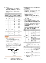
GS573
Function Code "03"
Specification for the
max. number of holding
register read times
0:125
1 to 125: Specify the maximum number.
Other than above: 125
GS574
Function Code "04"
Specification for the
max. number of input
register read times
0:125
1 to 125: Specify the maximum number.
Other than above: 125
GS575
Function Code "0F"
Specification for the
max. number of
multiple-coil write times
0:800
1 to 1968: Specify the maximum number.
Other than above: 1968
When Bit0 of GS570 is "1", the function
code "0F" is not used, and therefore the
setting of GS575 will be disabled.
GS576
Function Code "10"
Specification for the
max. number of
multiple-holding
register write times
0:100
1 to 123: Specify the maximum number.
Other than above: 123
When Bit1 of GS570 is "1", the function
code "10" is not used, and therefore the
setting of GS576 will be disabled.
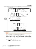
GS device
Description
Set value
Ch1 Ch2 Ch3 Ch4
GS
590
GS
597
GS
604
GS
611
Command selection
Bit0:
0
Using Function Code
"0F"
1
Not using Function
Code "0F"
Bit1:
0
Using Function Code
"10"
1
Not using Function
Code "10"
GS
591
GS
598
GS
605
GS
612
Function Code "01"
Specification for the
max. number of coil
read times
0:2000
1 to 2000: Specify the maximum
number.
Other than above: 2000
GS
592
GS
599
GS
606
GS
613
Function Code "02"
Specification for the
max. number of input
relay read times
0:2000
1 to 2000: Specify the maximum
number.
Other than above: 2000
GS
593
GS
600
GS
607
GS
614
Function Code "03"
Specification for the
max. number of
holding register read
times
0:125
1 to 125: Specify the maximum
number.
Other than above: 125
GS
594
GS
601
GS
608
GS
615
Function Code "04"
Specification for the
max. number of input
register read times
0:125
1 to 125: Specify the maximum
number.
Other than above: 125
GS
595
GS
602
GS
609
GS
616
Function Code "0F"
Specification for the
max. number of
multiple-coil write
times
0:800
1 to 1968: Specify the maximum
number.
Other than above: 1968
When Bit0 of GS570 is "1", the
function code "0F" is not used,
and therefore the setting of
GS575 will be disabled.
GS
device
Description
Set value
GS
596
GS
603
GS
610
GS
617
Function Code "10"
Specification for
the max. number of
multiple-holding
register write times
0:100
1 to 123: Specify the maximum
number.
Other than above: 123
When Bit1 of GS570 is "1", the
function code "10" is not used,
and therefore the setting of
GS576 will be disabled.
Specification range
1 to 247
Specification
station NO.
Compatible
device
Set value
248
GD10
0 to 255:
0: All station specification (broadcast)
255 : Host station access
For the setting other than the above, an
error (dedicated device is out of range) will
occur
249
GD11
250
GD12
251
GD13
252
GD14
253
GD15
254
GD16
GS device
Description
Set value
Ch1 Ch2 Ch3 Ch4
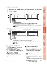
GOT
Examples of station number setting
Station
No.3
Station
No.15
Station
No.1
Summary of Contents for GT16
Page 1: ......
Page 2: ......
Page 46: ...1 4 1 OVERVIEW 1 1 Features ...
Page 54: ...2 8 2 SYSTEM CONFIGURATION 2 2 System Equipment ...
Page 60: ...3 6 3 SPECIFICATIONS 3 4 Battery specifications ...
Page 72: ...5 8 5 UL cUL STANDARDS AND EMC DIRECTIVE 5 2 EMC Directive ...
Page 102: ...6 30 6 OPTION 6 7 Connector Conversion Box ...
Page 106: ...7 4 7 INSTALLATION 7 1 Installing Procedure ...
Page 110: ...8 4 8 COMMUNICATION CABLE 8 1 Overview of Communication Cable ...
Page 130: ...9 20 9 HANDLING OF POWER WIRING AND SWITCH 9 4 Switch Wiring ...
Page 142: ...10 12 10 UTILITY FUNCTION 10 3 Utility Display ...
Page 184: ...11 42 11 DISPLAY AND OPERATION SETTINGS GOT SET UP 11 4 Maintenance Function ...
Page 202: ...12 18 12 COMMUNICATION INTERFACE SETTING COMMUNICATION SETTING 12 3 Ethernet Setting ...
Page 226: ...13 24 13 DEBUG 13 3 Memory Data Control ...
Page 248: ...14 22 14 SELF CHECK 14 2 Batch Self Check ...
Page 350: ...15 102 15 DATA CONTROL 15 3 OS Project Information ...
Page 410: ...19 22 19 TROUBLESHOOTING 19 2 Error Message and System Alarm ...
Page 418: ...App 8 APPENDICES Appendix 3 Transportation Precautions ...
Page 422: ...REVISIONS 4 ...
Page 425: ......
Page 426: ......
Page 427: ......
Page 428: ......
Page 470: ......
Page 510: ...21 22 21 COMPUTER LINK CONNECTION 21 6 Precautions ...
Page 568: ...22 58 22 ETHERNET CONNECTION 22 5 Precautions ...
Page 584: ......
Page 626: ...25 14 25 SERVO AMPLIFIER CONNECTION 25 7 Precautions ...
Page 632: ...26 6 26 ROBOT CONTROLLER CONNECTION 26 6 Precautions ...
Page 647: ...MULTIPLE GOT CONNECTIONS 29 GOT MULTI DROP CONNECTION 29 1 ...
Page 648: ......
Page 659: ...MULTI CHANNEL FUNCTION 30 MULTI CHANNEL FUNCTION 30 1 ...
Page 660: ......
Page 675: ...FA TRANSPARENT FUNCTION 31 FA TRANSPARENT FUNCTION 31 1 ...
Page 676: ......
Page 742: ...31 66 31 FA TRANSPARENT FUNCTION 31 7 Precautions ...
Page 744: ......
Page 766: ...32 22 32 CONNECTION TO IAI ROBOT CONTROLLER 32 7 Precautions ...
Page 802: ...34 10 34 CONNECTION TO OMRON TEMPERATURE CONTROLLER 34 7 Precautions ...
Page 834: ...36 18 36 CONNECTION TO KOYO EI PLC 36 6 Device Range that Can Be Set ...
Page 858: ...38 12 38 CONNECTION TO SHARP PLC 38 6 Device Range that Can Be Set ...
Page 868: ...39 10 39 CONNECTION TO SHINKO TECHNOS INDICATING CONTROLLER 39 7 Precautions ...
Page 902: ...42 6 42 CONNECTION TO TOSHIBA MACHINE PLC 42 6 Device Range that Can Be Set ...
Page 908: ...43 6 43 CONNECTION TO PANASONIC SERVO AMPLIFIER 43 7 Precautions ...
Page 970: ...48 12 48 CONNECTION TO FUJI TEMPERATURE CONTROLLER 48 7 Precautions ...
Page 1052: ...52 26 52 CONNECTION TO AZBIL CONTROL EQUIPMENT 52 7 Precautions ...
Page 1102: ...55 14 55 CONNECTION TO GE PLC 55 7 Precautions ...
Page 1114: ...57 4 57 CONNECTION TO SICK SAFETY CONTROLLER 57 5 Device Range that Can Be Set ...
Page 1128: ...59 2 59 CONNECTION TO HIRATA CORPORATION HNC CONTROLLER ...
Page 1130: ...60 2 60 CONNECTION TO MURATEC CONTROLLER ...
Page 1132: ......
Page 1270: ...62 68 62 MICROCOMPUTER CONNECTION ETHERNET 62 8 Precautions ...
Page 1271: ...MODBUS CONNECTIONS 63 MODBUS R RTU CONNECTION 63 1 64 MODBUS R TCP CONNECTION 64 1 ...
Page 1272: ......
Page 1292: ...64 12 64 MODBUS R TCP CONNECTION 64 7 Precautions ...
Page 1293: ...CONNECTIONS TO PERIPHERAL EQUIPMENT 65 VNC R SERVER CONNECTION 65 1 ...
Page 1294: ......
Page 1298: ...65 4 65 VNC R SERVER CONNECTION 65 4 Setting in Personal Computer ...
Page 1302: ...REVISIONS 4 ...
Page 1305: ......
Page 1306: ......


