


A - 39
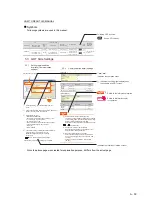
HOW TO READ THIS MANUAL
Symbols
Following symbols are used in this manual.
Since the above page was created for explanation purpose, it differs from the actual page.
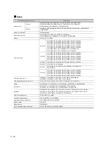
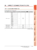
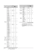
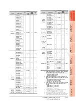
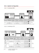
PLC
Connection cable
Connector
conversion box
External cable
GOT
Total
distance
Number of
connectable
equipment
Model name
RS-422 connector
conversion Cable
Commun
ication
type
Cable model
MELSEC-Q
-
RS-232
GT01-C30R2-6P (3m)
GT16H-CNB-42S
GT16H-C30-42P (3m)
6m
1 GOT for 1 computer
link module
FA-CNV2402CBL (0.2m)
FA-CNV2405CBL (0.5m)
RS-422
GT01-C30R4-25P (3m)
GT01-C100R4-25P (10m)
GT16H-CNB-42S
GT16H-C30-42P (3m)
GT16H-C60-42P (6m)
GT16H-C100-42P (10m)
13.5m
5.3 GOT Side Settings
5.3.1
Setting communication
interface (Communication
settings)
Set the channel of the connected equipment.
1.
Select [Common]
→
[Controller Setting] from the
menu.
2.
The Controller Setting window is displayed. Select the
channel to be used from the list menu.
3.
Set the following items.
• Manufacturer: Mitsubishi
• Controller Type: Set the option according to the
Controller Type to be connected.
• I/F: Interface to be used
• Driver: Set either of the following option according
to the Controller Type to be connected.
• BUS (Q)
• BUS (A/QnA)
4.
The detailed setting is displayed after Manufacturer,
Controller Type, I/F, and Driver are set.
Make the settings according to the usage
environment.
5.3.2 Communication detail settings
Click the [OK] button when settings are completed.
5.3.2
Communication detail settings
(1) Bus (Q)
(2) Bus(A/QnA)
(1) Communication interface setting by Utility
The communication interface setting can be changed
on the Utility's [Communication Settings] after writing
[Communication Settings] of project data.
For details on the Utility, refer to the following manual.
GT User's Manual
(2) Precedence in communication settings
When settings are made by GT Designer3 or the
Utility, the latest setting is effective.
(3) When changing Stage No. and Slot No.
Change these settings with the PLC CPU turned
OFF, and then reapply the power to the PLC CPU
and GOT.
Failure to do so may generate a system alarm
(No.487).
Item
Description
Range
Item
Description
Range
7
to
1
(Default: 1)
Number of
stages
Number of
stages
9
to
0
(Default: 0)
(Default: Normal)
High/Normal/Low
Slot No.
Slot No.
Monitor speed
7
to
1
(Default: 1)
7
to
0
(Default: 0)
Indicates the location of related content.
Indicates the operation steps.
[ ] : Indicates the setting items displayed on
the software and GOT screen.
1. 2. 3.
…
Following GOT is shown.
Shows GT16 Handy.
Refers to the information required.
Refers to information useful
for operation.
2.
3.
4.
Click!
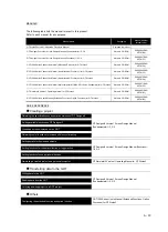
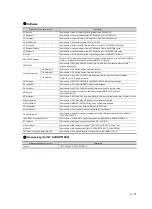
Summary of Contents for GT16
Page 1: ......
Page 2: ......
Page 46: ...1 4 1 OVERVIEW 1 1 Features ...
Page 54: ...2 8 2 SYSTEM CONFIGURATION 2 2 System Equipment ...
Page 60: ...3 6 3 SPECIFICATIONS 3 4 Battery specifications ...
Page 72: ...5 8 5 UL cUL STANDARDS AND EMC DIRECTIVE 5 2 EMC Directive ...
Page 102: ...6 30 6 OPTION 6 7 Connector Conversion Box ...
Page 106: ...7 4 7 INSTALLATION 7 1 Installing Procedure ...
Page 110: ...8 4 8 COMMUNICATION CABLE 8 1 Overview of Communication Cable ...
Page 130: ...9 20 9 HANDLING OF POWER WIRING AND SWITCH 9 4 Switch Wiring ...
Page 142: ...10 12 10 UTILITY FUNCTION 10 3 Utility Display ...
Page 184: ...11 42 11 DISPLAY AND OPERATION SETTINGS GOT SET UP 11 4 Maintenance Function ...
Page 202: ...12 18 12 COMMUNICATION INTERFACE SETTING COMMUNICATION SETTING 12 3 Ethernet Setting ...
Page 226: ...13 24 13 DEBUG 13 3 Memory Data Control ...
Page 248: ...14 22 14 SELF CHECK 14 2 Batch Self Check ...
Page 350: ...15 102 15 DATA CONTROL 15 3 OS Project Information ...
Page 410: ...19 22 19 TROUBLESHOOTING 19 2 Error Message and System Alarm ...
Page 418: ...App 8 APPENDICES Appendix 3 Transportation Precautions ...
Page 422: ...REVISIONS 4 ...
Page 425: ......
Page 426: ......
Page 427: ......
Page 428: ......
Page 470: ......
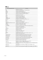
Page 510: ...21 22 21 COMPUTER LINK CONNECTION 21 6 Precautions ...
Page 568: ...22 58 22 ETHERNET CONNECTION 22 5 Precautions ...
Page 584: ......
Page 626: ...25 14 25 SERVO AMPLIFIER CONNECTION 25 7 Precautions ...
Page 632: ...26 6 26 ROBOT CONTROLLER CONNECTION 26 6 Precautions ...
Page 647: ...MULTIPLE GOT CONNECTIONS 29 GOT MULTI DROP CONNECTION 29 1 ...
Page 648: ......
Page 659: ...MULTI CHANNEL FUNCTION 30 MULTI CHANNEL FUNCTION 30 1 ...
Page 660: ......
Page 675: ...FA TRANSPARENT FUNCTION 31 FA TRANSPARENT FUNCTION 31 1 ...
Page 676: ......
Page 742: ...31 66 31 FA TRANSPARENT FUNCTION 31 7 Precautions ...
Page 744: ......
Page 766: ...32 22 32 CONNECTION TO IAI ROBOT CONTROLLER 32 7 Precautions ...
Page 802: ...34 10 34 CONNECTION TO OMRON TEMPERATURE CONTROLLER 34 7 Precautions ...
Page 834: ...36 18 36 CONNECTION TO KOYO EI PLC 36 6 Device Range that Can Be Set ...
Page 858: ...38 12 38 CONNECTION TO SHARP PLC 38 6 Device Range that Can Be Set ...
Page 868: ...39 10 39 CONNECTION TO SHINKO TECHNOS INDICATING CONTROLLER 39 7 Precautions ...
Page 902: ...42 6 42 CONNECTION TO TOSHIBA MACHINE PLC 42 6 Device Range that Can Be Set ...
Page 908: ...43 6 43 CONNECTION TO PANASONIC SERVO AMPLIFIER 43 7 Precautions ...
Page 970: ...48 12 48 CONNECTION TO FUJI TEMPERATURE CONTROLLER 48 7 Precautions ...
Page 1052: ...52 26 52 CONNECTION TO AZBIL CONTROL EQUIPMENT 52 7 Precautions ...
Page 1102: ...55 14 55 CONNECTION TO GE PLC 55 7 Precautions ...
Page 1114: ...57 4 57 CONNECTION TO SICK SAFETY CONTROLLER 57 5 Device Range that Can Be Set ...
Page 1128: ...59 2 59 CONNECTION TO HIRATA CORPORATION HNC CONTROLLER ...
Page 1130: ...60 2 60 CONNECTION TO MURATEC CONTROLLER ...
Page 1132: ......
Page 1270: ...62 68 62 MICROCOMPUTER CONNECTION ETHERNET 62 8 Precautions ...
Page 1271: ...MODBUS CONNECTIONS 63 MODBUS R RTU CONNECTION 63 1 64 MODBUS R TCP CONNECTION 64 1 ...
Page 1272: ......
Page 1292: ...64 12 64 MODBUS R TCP CONNECTION 64 7 Precautions ...
Page 1293: ...CONNECTIONS TO PERIPHERAL EQUIPMENT 65 VNC R SERVER CONNECTION 65 1 ...
Page 1294: ......
Page 1298: ...65 4 65 VNC R SERVER CONNECTION 65 4 Setting in Personal Computer ...
Page 1302: ...REVISIONS 4 ...
Page 1305: ......
Page 1306: ......


