


61. MICROCOMPUTER CONNECTION (SERIAL)
61.4 Device Data Area
61 - 11
60
CONNECTION T
O
MURA
T
E
C
CONTROLL
ER
61
MI
C
R
O
C
OMPUTER
CONNECTION
(SE
R
IA
L)
62
MICR
OCOMPUTER
CONNECTION
(E
T
HE
RN
E
T)
63
MO
D
B
US(R)/
R
T
U
CONNE
C
T
ION
64
MO
DBUS(R)/
TCP
CON
N
E
C
T
ION
65
V
NC(R) S
E
R
V
E
R
CONNECTION
61.4.5 SD devices
The SD devices are word devices into which GOT communication errors (error codes), clock data and other information
are stored.
List of SD devices
The following lists the SD devices (virtual devices inside the GOT).
*1
For details and corrective actions for the errors (error codes) that are stored into SD2, refer to the following:
■
Details and actions for errors (error codes) stored into SD2
*2
If a wrong day of the week is set by the clock data setting commands, the clock data will differ from the time displayed on the
utility.
Example: When June 1, 2004 (Thursday) is set by the clock data setting command (the actual day of the week is Tuesday),
"4" is stored to SD9 although Tuesday (TUE) will be displayed on the utility time display.
POINT
POINT
POINT
The side where virtual devices are set
System
: Set on the system side.
User
: Set on the user side (by sending request messages from host or using the touch switches, etc.
on the GOT).
Address
Description
Set side
SD0
SD1
100ms counter (32bits)
The counter is incremented at 100ms intervals after GOT is turned ON.
(The time elapsed after GOT is turned ON is stored in 100ms units.)
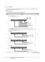
(1) When setting the LH order to [32bit Storage] for the communication detail settings
The lower and upper bits are stored in SD0 and SD1 respectively.
(2) When setting the HL order to [32bit Storage] for the communication detail settings
The upper and lower bits are stored in SD0 and SD1 respectively.
System
SD2
*1
Communication error status
An error data (error code) occurred during communication is stored.
•Host Address (Communication error that occurred on the request destination GOT)
0: No error
1: Parity error
2: Framing error
3: Overrun error
4: Communication message error
5: Command error
6: Clock data setting error
•Other station (Communication error that occurred on another GOT when multiple GOTs are connected)
101: Parity error
102: Framing error
103: Overrun error
104: Communication message error
105: Timeout error (No station of the specified address exists.)
106: Multiple units not connectable 107: Clock data setting error
SD3
Clock data (second): Second data of 00 to 59 is stored.
SD4
Clock data (minute): Minute data of 00 to 59 is stored.
SD5
Clock data (hour): Hour data of 00 to 23 is stored.
SD6
Clock data (day): Day data of 00 to 31 is stored.
SD7
Clock data (month): Month data of 01 to 12 is stored.
SD8
Clock data (year)
4-digit year data is stored.
System
SD9
Clock data (day of week)
*2
Day-of-the-week data is stored.
0: Sunday
1: Monday
2: Tuesday
3: Wednesday
4: Thursday
5: Friday
6: Saturday
SD10 to 15
Unused
―
SD0
SD1
Lower word
Upper word
SD1
SD0
Lower word
Upper word
Summary of Contents for GT16
Page 1: ......
Page 2: ......
Page 46: ...1 4 1 OVERVIEW 1 1 Features ...
Page 54: ...2 8 2 SYSTEM CONFIGURATION 2 2 System Equipment ...
Page 60: ...3 6 3 SPECIFICATIONS 3 4 Battery specifications ...
Page 72: ...5 8 5 UL cUL STANDARDS AND EMC DIRECTIVE 5 2 EMC Directive ...
Page 102: ...6 30 6 OPTION 6 7 Connector Conversion Box ...
Page 106: ...7 4 7 INSTALLATION 7 1 Installing Procedure ...
Page 110: ...8 4 8 COMMUNICATION CABLE 8 1 Overview of Communication Cable ...
Page 130: ...9 20 9 HANDLING OF POWER WIRING AND SWITCH 9 4 Switch Wiring ...
Page 142: ...10 12 10 UTILITY FUNCTION 10 3 Utility Display ...
Page 184: ...11 42 11 DISPLAY AND OPERATION SETTINGS GOT SET UP 11 4 Maintenance Function ...
Page 202: ...12 18 12 COMMUNICATION INTERFACE SETTING COMMUNICATION SETTING 12 3 Ethernet Setting ...
Page 226: ...13 24 13 DEBUG 13 3 Memory Data Control ...
Page 248: ...14 22 14 SELF CHECK 14 2 Batch Self Check ...
Page 350: ...15 102 15 DATA CONTROL 15 3 OS Project Information ...
Page 410: ...19 22 19 TROUBLESHOOTING 19 2 Error Message and System Alarm ...
Page 418: ...App 8 APPENDICES Appendix 3 Transportation Precautions ...
Page 422: ...REVISIONS 4 ...
Page 425: ......
Page 426: ......
Page 427: ......
Page 428: ......
Page 470: ......
Page 510: ...21 22 21 COMPUTER LINK CONNECTION 21 6 Precautions ...
Page 568: ...22 58 22 ETHERNET CONNECTION 22 5 Precautions ...
Page 584: ......
Page 626: ...25 14 25 SERVO AMPLIFIER CONNECTION 25 7 Precautions ...
Page 632: ...26 6 26 ROBOT CONTROLLER CONNECTION 26 6 Precautions ...
Page 647: ...MULTIPLE GOT CONNECTIONS 29 GOT MULTI DROP CONNECTION 29 1 ...
Page 648: ......
Page 659: ...MULTI CHANNEL FUNCTION 30 MULTI CHANNEL FUNCTION 30 1 ...
Page 660: ......
Page 675: ...FA TRANSPARENT FUNCTION 31 FA TRANSPARENT FUNCTION 31 1 ...
Page 676: ......
Page 742: ...31 66 31 FA TRANSPARENT FUNCTION 31 7 Precautions ...
Page 744: ......
Page 766: ...32 22 32 CONNECTION TO IAI ROBOT CONTROLLER 32 7 Precautions ...
Page 802: ...34 10 34 CONNECTION TO OMRON TEMPERATURE CONTROLLER 34 7 Precautions ...
Page 834: ...36 18 36 CONNECTION TO KOYO EI PLC 36 6 Device Range that Can Be Set ...
Page 858: ...38 12 38 CONNECTION TO SHARP PLC 38 6 Device Range that Can Be Set ...
Page 868: ...39 10 39 CONNECTION TO SHINKO TECHNOS INDICATING CONTROLLER 39 7 Precautions ...
Page 902: ...42 6 42 CONNECTION TO TOSHIBA MACHINE PLC 42 6 Device Range that Can Be Set ...
Page 908: ...43 6 43 CONNECTION TO PANASONIC SERVO AMPLIFIER 43 7 Precautions ...
Page 970: ...48 12 48 CONNECTION TO FUJI TEMPERATURE CONTROLLER 48 7 Precautions ...
Page 1052: ...52 26 52 CONNECTION TO AZBIL CONTROL EQUIPMENT 52 7 Precautions ...
Page 1102: ...55 14 55 CONNECTION TO GE PLC 55 7 Precautions ...
Page 1114: ...57 4 57 CONNECTION TO SICK SAFETY CONTROLLER 57 5 Device Range that Can Be Set ...
Page 1128: ...59 2 59 CONNECTION TO HIRATA CORPORATION HNC CONTROLLER ...
Page 1130: ...60 2 60 CONNECTION TO MURATEC CONTROLLER ...
Page 1132: ......
Page 1270: ...62 68 62 MICROCOMPUTER CONNECTION ETHERNET 62 8 Precautions ...
Page 1271: ...MODBUS CONNECTIONS 63 MODBUS R RTU CONNECTION 63 1 64 MODBUS R TCP CONNECTION 64 1 ...
Page 1272: ......
Page 1292: ...64 12 64 MODBUS R TCP CONNECTION 64 7 Precautions ...
Page 1293: ...CONNECTIONS TO PERIPHERAL EQUIPMENT 65 VNC R SERVER CONNECTION 65 1 ...
Page 1294: ......
Page 1298: ...65 4 65 VNC R SERVER CONNECTION 65 4 Setting in Personal Computer ...
Page 1302: ...REVISIONS 4 ...
Page 1305: ......
Page 1306: ......


