


63 - 6
63. MODBUS(R)/RTU CONNECTION
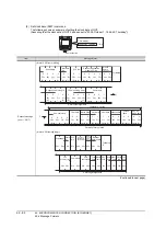
63.5 MODBUS/RTU Equipment Side Setting
Address
GT Designer3 converts the device numbers into
decimal format according to the address map of the
MODBUS equipment to be used.
The table below shows the representations on the
MODBUS/RTU communication protocol and GT
Designer3.
POINT
POINT
POINT
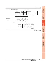
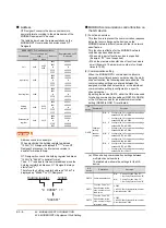
Address conversion example
When monitoring the holding register's address
"1234H," GT Designer3 displays "4*****" since GT
Designer3 processes the internal conversion in
decimal format as follows:
GT Designer3 converts the holding register's address
"1234H" to "04660" in decimal format.
Then, "+1" is added to this decimal address since the
holding register's address on GT Designer3 always
starts from "1."
Therefore, the holding register's address "1234H" is
displayed as "404661" on GT Designer3.
MODBUS communication control function on
the GS device
(1) Functions overview
This function is to prevent the communication response
delay that occurs because the devices on the
MODBUS network differs from each other in network
specification.
This function is effective for the MODBUS network
conditions as described below:
• When only a part of function codes is supported
(Example: "0F" is not supported)
• When the maximum transfer size of function code is
small (Example: The maximum number of coil read
times is 1000)
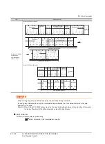
(2) Communication setting
When the MODBUS/RTU communication driver is
assigned to multiple channel numbers using the multi-
channel function, the following cases are possible. The
communication settings are shared between the
assigned multiple channel numbers, or the individual
communication setting is configured to a specific
channel number.
By setting the device GS579, either the GS device used
for sharing communication settings (GS570 to GS576)
or the GS device used for individual communication
setting (GS590 to GS617) is validated.
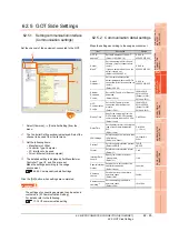
(a) When sharing communication settings between
multiple channel numbers
The table below shows the settings for the GS
device.
MODBUS/RTU Communication protocol
Representation on GT
Designer3
Device name
Function code to be
used
Address
Read
Write
Coil
0x01
0x05
0x0F
0000
0001
to
FFFE
FFFF
000001
000002
to
065535
065536
Input relay
0x02
-
0000
0001
to
FFFE
FFFF
100001
100002
to
165535
165536
Input register
0x04
-
0000
0001
to
FFFE
FFFF
300001
300002
to
365535
365536
Holding
register
0x03
0x06
0x10
0000
0001
to
FFFE
FFFF
400001
400002
to
465535
465536
Extension file
register
0x14
0x15
0000
0001
to
270E
270F
600000
600001
to
609998
609999
Holding register
"4 04660" +1
"404661"
1234H
GS
device
Description
Set value
GS579
Validity of
setting
channel
number
Bit0:
0 Configure the Ch1 communication settings
between GS570 to GS576.
1 Configure the Ch1 communication settings
between GS590 to GS596.
Bit1:
0 Configure the Ch2 communication settings
between GS570 to GS576.
1 Configure the Ch2 communication settings
between GS590 to GS603.
Bit2:
0 Configure the Ch3 communication settings
between GS570 to GS576.
1 Configure the Ch3 communication settings
between GS604 to GS610
Bit3:
0 Configure the Ch4 communication settings
between GS570 to GS576.
1 Configure the Ch4 communication settings
between GS611 to GS617.
GS
device
Description
Set value
GS570 Command selection
Bit0:
0
Using Function Code "0F"
1
Not using Function Code "0F"
Bit1:
0
Using Function Code "10"
1
Not using Function Code "10"
GS571
Function Code "01"
Specification for the
max. number of coil
read times
0:2000
1 to 2000: Specify the maximum number.
Other than above: 2000
GS572
Function Code "02"
Specification for the
max. number of input
relay read times
0:2000
1 to 2000: Specify the maximum number.
Other than above: 2000
Summary of Contents for GT16
Page 1: ......
Page 2: ......
Page 46: ...1 4 1 OVERVIEW 1 1 Features ...
Page 54: ...2 8 2 SYSTEM CONFIGURATION 2 2 System Equipment ...
Page 60: ...3 6 3 SPECIFICATIONS 3 4 Battery specifications ...
Page 72: ...5 8 5 UL cUL STANDARDS AND EMC DIRECTIVE 5 2 EMC Directive ...
Page 102: ...6 30 6 OPTION 6 7 Connector Conversion Box ...
Page 106: ...7 4 7 INSTALLATION 7 1 Installing Procedure ...
Page 110: ...8 4 8 COMMUNICATION CABLE 8 1 Overview of Communication Cable ...
Page 130: ...9 20 9 HANDLING OF POWER WIRING AND SWITCH 9 4 Switch Wiring ...
Page 142: ...10 12 10 UTILITY FUNCTION 10 3 Utility Display ...
Page 184: ...11 42 11 DISPLAY AND OPERATION SETTINGS GOT SET UP 11 4 Maintenance Function ...
Page 202: ...12 18 12 COMMUNICATION INTERFACE SETTING COMMUNICATION SETTING 12 3 Ethernet Setting ...
Page 226: ...13 24 13 DEBUG 13 3 Memory Data Control ...
Page 248: ...14 22 14 SELF CHECK 14 2 Batch Self Check ...
Page 350: ...15 102 15 DATA CONTROL 15 3 OS Project Information ...
Page 410: ...19 22 19 TROUBLESHOOTING 19 2 Error Message and System Alarm ...
Page 418: ...App 8 APPENDICES Appendix 3 Transportation Precautions ...
Page 422: ...REVISIONS 4 ...
Page 425: ......
Page 426: ......
Page 427: ......
Page 428: ......
Page 470: ......
Page 510: ...21 22 21 COMPUTER LINK CONNECTION 21 6 Precautions ...
Page 568: ...22 58 22 ETHERNET CONNECTION 22 5 Precautions ...
Page 584: ......
Page 626: ...25 14 25 SERVO AMPLIFIER CONNECTION 25 7 Precautions ...
Page 632: ...26 6 26 ROBOT CONTROLLER CONNECTION 26 6 Precautions ...
Page 647: ...MULTIPLE GOT CONNECTIONS 29 GOT MULTI DROP CONNECTION 29 1 ...
Page 648: ......
Page 659: ...MULTI CHANNEL FUNCTION 30 MULTI CHANNEL FUNCTION 30 1 ...
Page 660: ......
Page 675: ...FA TRANSPARENT FUNCTION 31 FA TRANSPARENT FUNCTION 31 1 ...
Page 676: ......
Page 742: ...31 66 31 FA TRANSPARENT FUNCTION 31 7 Precautions ...
Page 744: ......
Page 766: ...32 22 32 CONNECTION TO IAI ROBOT CONTROLLER 32 7 Precautions ...
Page 802: ...34 10 34 CONNECTION TO OMRON TEMPERATURE CONTROLLER 34 7 Precautions ...
Page 834: ...36 18 36 CONNECTION TO KOYO EI PLC 36 6 Device Range that Can Be Set ...
Page 858: ...38 12 38 CONNECTION TO SHARP PLC 38 6 Device Range that Can Be Set ...
Page 868: ...39 10 39 CONNECTION TO SHINKO TECHNOS INDICATING CONTROLLER 39 7 Precautions ...
Page 902: ...42 6 42 CONNECTION TO TOSHIBA MACHINE PLC 42 6 Device Range that Can Be Set ...
Page 908: ...43 6 43 CONNECTION TO PANASONIC SERVO AMPLIFIER 43 7 Precautions ...
Page 970: ...48 12 48 CONNECTION TO FUJI TEMPERATURE CONTROLLER 48 7 Precautions ...
Page 1052: ...52 26 52 CONNECTION TO AZBIL CONTROL EQUIPMENT 52 7 Precautions ...
Page 1102: ...55 14 55 CONNECTION TO GE PLC 55 7 Precautions ...
Page 1114: ...57 4 57 CONNECTION TO SICK SAFETY CONTROLLER 57 5 Device Range that Can Be Set ...
Page 1128: ...59 2 59 CONNECTION TO HIRATA CORPORATION HNC CONTROLLER ...
Page 1130: ...60 2 60 CONNECTION TO MURATEC CONTROLLER ...
Page 1132: ......
Page 1270: ...62 68 62 MICROCOMPUTER CONNECTION ETHERNET 62 8 Precautions ...
Page 1271: ...MODBUS CONNECTIONS 63 MODBUS R RTU CONNECTION 63 1 64 MODBUS R TCP CONNECTION 64 1 ...
Page 1272: ......
Page 1292: ...64 12 64 MODBUS R TCP CONNECTION 64 7 Precautions ...
Page 1293: ...CONNECTIONS TO PERIPHERAL EQUIPMENT 65 VNC R SERVER CONNECTION 65 1 ...
Page 1294: ......
Page 1298: ...65 4 65 VNC R SERVER CONNECTION 65 4 Setting in Personal Computer ...
Page 1302: ...REVISIONS 4 ...
Page 1305: ......
Page 1306: ......


