


3. SPECIFICATIONS
3.2 Performance Specifications
3 - 3
1
OV
ER
VI
EW
2
SY
STEM
CONFIGURA
TION
3
SP
ECI
F
IC
A
T
IO
NS
4
PA
R
T
S
N
A
M
E
5
UL, c
U
L
S
TANDARDS
A
N
D
E
MC
DIRECTIVE
6
OP
TIO
N
7
INST
ALL
A
TI
ON
8
COMMUNICA
TION
CABLE
*1
Bright dots (always lit) and dark dots (unlit) may appear on a liquid crystal display panel due to its characteristics. It is impossible
to completely avoid this symptom, as the liquid crystal display comprises of a great number of display elements. Flickers may be
observed depending on the display color.
Please note that these dots appear due to its characteristic and are not caused by product defect.
Flickers and partial discoloration may be generated on the liquid crystal display panel due to the display contents or the contrast
adjustment. However, please note that these phenomena appear due to its characteristic and are not caused by product defect.
There is a difference in the display brightness and the color tones between liquid crystal display panels. When using multiple
liquid crystal display panels, please note that there is an individual difference between them.
A crosstalk (shadow as an extension of the display) may appear on the liquid crystal display panel. Please note hat it appears due
to its characteristic.
When the display section is seen from the outside of the display angle, the display color seems like it has changed. Please note
that it is due to its characteristic.
Please note that the response time, brightness and color of the liquid crystal display panel may vary depending on the usage
environmental temperature.
When the same screen is displayed for a long time, an incidental color or partial discoloration is generated on the screen due to
heat damage, and it may not disappear.
To prevent the heat damage, the screen saver function is effective.
For details on the screen saver function, refer to the following.
*2
Gradation inversion is a characteristic of liquid crystal displays. Please be forewarned that depending on the displayed color, the
visualization may be difficult even within the described view angle.
*3
The GOT screen saving/backlight off function prevents images from becoming permanently etched on the display screen.
*4
The touch panel is analog resistive film-type. If you touch the panel simultaneously in 2 points or more, the switch that is located
around the center of the touched point, if any, may operate. Do not touch the panel in 2 points or more simultaneously.
*5
ROM in which new data can be written without deleting the written data.
*6
Note that this does not guarantee all user’s operation environment. The protection is not applied when the interface environment
protection cover or environment protection back cover is removed. In addition, the product may not be used in environments
under exposition of oil or chemicals for a long period of time, or in environments filled with oil-mist.
*7
If the operating ambient temperature is other than 25
, the error may become large.
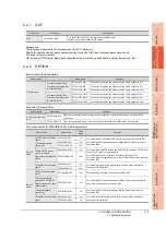
Built-in
interface
RS-232
RS-422/485
RS-232, RS-422/485, 1ch each
Transmission speed: 115200/57600/38400/19200/9600/4800bps
Connector shape: Square 42 pins (Male)
Application: For communicating with a controller (Select either RS-232 or RS-422/485 when
used)
Ethernet
Data transfer method: 100BASE-TX, 10BASE-T, 1ch
Connector shape: Square 42 pins (Male)
Application: For communicating with a controller, using the gateway function, or connecting a
personal computer (Project data upload/download, OS installation)
USB
USB(Full Speed 12Mbps), Host, 1ch
Connector shape: TYPE-A
Application: Data transfer, data storage
USB(Full Speed 12Mbps), device 1ch
Connector shape: Mini-B
Application: For connecting a personal computer (Project data upload/download, OS
installation, FA transparent function)
CF card
Compact flash slot 1ch
Connector shape: TYPE I
Application: Data transfer, data storage, GOT startup
Buzzer output
Single tone (tone length adjustable)
Protective structure
*6
IP65f
(valid when the external cable is connected, except for the connector conversion box side)
External dimensions
(Excluding projections such as the
emergency stop switch)
201(7.91)(W)×230(9.06)(H)×97(3.82)(D)[mm](inch)
Weight
Approx. 1.2kg (GT16 Handy main unit only)
Compatible software package
(GT Designer3 version)
Version1.14Q or later
Item
Specifications
Summary of Contents for GT16
Page 1: ......
Page 2: ......
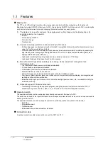
Page 46: ...1 4 1 OVERVIEW 1 1 Features ...
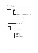
Page 54: ...2 8 2 SYSTEM CONFIGURATION 2 2 System Equipment ...
Page 60: ...3 6 3 SPECIFICATIONS 3 4 Battery specifications ...
Page 72: ...5 8 5 UL cUL STANDARDS AND EMC DIRECTIVE 5 2 EMC Directive ...
Page 102: ...6 30 6 OPTION 6 7 Connector Conversion Box ...
Page 106: ...7 4 7 INSTALLATION 7 1 Installing Procedure ...
Page 110: ...8 4 8 COMMUNICATION CABLE 8 1 Overview of Communication Cable ...
Page 130: ...9 20 9 HANDLING OF POWER WIRING AND SWITCH 9 4 Switch Wiring ...
Page 142: ...10 12 10 UTILITY FUNCTION 10 3 Utility Display ...
Page 184: ...11 42 11 DISPLAY AND OPERATION SETTINGS GOT SET UP 11 4 Maintenance Function ...
Page 202: ...12 18 12 COMMUNICATION INTERFACE SETTING COMMUNICATION SETTING 12 3 Ethernet Setting ...
Page 226: ...13 24 13 DEBUG 13 3 Memory Data Control ...
Page 248: ...14 22 14 SELF CHECK 14 2 Batch Self Check ...
Page 350: ...15 102 15 DATA CONTROL 15 3 OS Project Information ...
Page 410: ...19 22 19 TROUBLESHOOTING 19 2 Error Message and System Alarm ...
Page 418: ...App 8 APPENDICES Appendix 3 Transportation Precautions ...
Page 422: ...REVISIONS 4 ...
Page 425: ......
Page 426: ......
Page 427: ......
Page 428: ......
Page 470: ......
Page 510: ...21 22 21 COMPUTER LINK CONNECTION 21 6 Precautions ...
Page 568: ...22 58 22 ETHERNET CONNECTION 22 5 Precautions ...
Page 584: ......
Page 626: ...25 14 25 SERVO AMPLIFIER CONNECTION 25 7 Precautions ...
Page 632: ...26 6 26 ROBOT CONTROLLER CONNECTION 26 6 Precautions ...
Page 647: ...MULTIPLE GOT CONNECTIONS 29 GOT MULTI DROP CONNECTION 29 1 ...
Page 648: ......
Page 659: ...MULTI CHANNEL FUNCTION 30 MULTI CHANNEL FUNCTION 30 1 ...
Page 660: ......
Page 675: ...FA TRANSPARENT FUNCTION 31 FA TRANSPARENT FUNCTION 31 1 ...
Page 676: ......
Page 742: ...31 66 31 FA TRANSPARENT FUNCTION 31 7 Precautions ...
Page 744: ......
Page 766: ...32 22 32 CONNECTION TO IAI ROBOT CONTROLLER 32 7 Precautions ...
Page 802: ...34 10 34 CONNECTION TO OMRON TEMPERATURE CONTROLLER 34 7 Precautions ...
Page 834: ...36 18 36 CONNECTION TO KOYO EI PLC 36 6 Device Range that Can Be Set ...
Page 858: ...38 12 38 CONNECTION TO SHARP PLC 38 6 Device Range that Can Be Set ...
Page 868: ...39 10 39 CONNECTION TO SHINKO TECHNOS INDICATING CONTROLLER 39 7 Precautions ...
Page 902: ...42 6 42 CONNECTION TO TOSHIBA MACHINE PLC 42 6 Device Range that Can Be Set ...
Page 908: ...43 6 43 CONNECTION TO PANASONIC SERVO AMPLIFIER 43 7 Precautions ...
Page 970: ...48 12 48 CONNECTION TO FUJI TEMPERATURE CONTROLLER 48 7 Precautions ...
Page 1052: ...52 26 52 CONNECTION TO AZBIL CONTROL EQUIPMENT 52 7 Precautions ...
Page 1102: ...55 14 55 CONNECTION TO GE PLC 55 7 Precautions ...
Page 1114: ...57 4 57 CONNECTION TO SICK SAFETY CONTROLLER 57 5 Device Range that Can Be Set ...
Page 1128: ...59 2 59 CONNECTION TO HIRATA CORPORATION HNC CONTROLLER ...
Page 1130: ...60 2 60 CONNECTION TO MURATEC CONTROLLER ...
Page 1132: ......
Page 1270: ...62 68 62 MICROCOMPUTER CONNECTION ETHERNET 62 8 Precautions ...
Page 1271: ...MODBUS CONNECTIONS 63 MODBUS R RTU CONNECTION 63 1 64 MODBUS R TCP CONNECTION 64 1 ...
Page 1272: ......
Page 1292: ...64 12 64 MODBUS R TCP CONNECTION 64 7 Precautions ...
Page 1293: ...CONNECTIONS TO PERIPHERAL EQUIPMENT 65 VNC R SERVER CONNECTION 65 1 ...
Page 1294: ......
Page 1298: ...65 4 65 VNC R SERVER CONNECTION 65 4 Setting in Personal Computer ...
Page 1302: ...REVISIONS 4 ...
Page 1305: ......
Page 1306: ......


