


16 - 4
16. INSTALLATION OF COREOS, BOOTOS AND STANDARD MONITOR OS
16.3 BootOS and Standard Monitor OS Installation Using CF Card or USB Memory
16.3 BootOS and Standard Monitor OS Installation Using
CF Card or USB Memory
There are the following two types for the BootOS, standard monitor OS installation using the CF card or USB memory.
(1) Installing when starting the GOT
(
16.3.1 Installing when starting the GOT)
All the OS and project data stored in the CF card or USB memory are transferred to the GOT when powering on
the GOT. This installing method is effective in the following cases.
• The GOT utility cannot be displayed.
• The standard monitor OS is not installed.
(2) Installing using the data control function (Utility)
(
16.3.2 Installing using the data control function (Utility))
By operating the utility, select OS or project data stored in the CF card or USB memory and transfer them to the
GOT.
POINT
POINT
POINT
Precautions on installing BootOS, standard monitor OS
(1) Installing both BootOS and standard monitor OS
After completing BootOS installation, install standard monitor OS.
When installing BootOS, the built-in flash memory in the GOT is initialized and goes to the status at factory
shipment. (All OS and project data are erased.)
(2) Copying project data using CF card or USB memory
After installing BootOS, standard monitor OS, and other OS, download the project data.
At this time, match the version of the standard monitor OS in the GOT with the version of the standard monitor
OS with which the project data was created.
(3) When OS and project data are in the CF card or USB memory (when using GT Designer3)
For S.MODE switch-pressing installation, after the OS installation is complete, the project data is downloaded.
When installing with the utility, install the OS and download the project data from their respective operation
screens.
(4) Installation cannot be interrupted.
Do not perform any of the following during a BootOS or standard monitor OS installation.
Failure to do so may result in installation failure, causing the GOT malfunction.
• Powering off the GOT
• Pressing the reset button of the GOT
• Turning off the CF card access switch of the GOT
• Removing the CF card or USB memory
If the installation failure and the GOT malfunction occur, take the following action.
• If BootOS installation failed:
Install CoreOS.
(
• If standard monitor OS installation failed:
Install BootOS.
(
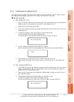
16.3.1 Installing when starting the GOT)
BootOS is installed in the GOT at factory shipment. It is not necessary to install BootOS when not upgrading it.
Summary of Contents for GT16
Page 1: ......
Page 2: ......
Page 46: ...1 4 1 OVERVIEW 1 1 Features ...
Page 54: ...2 8 2 SYSTEM CONFIGURATION 2 2 System Equipment ...
Page 60: ...3 6 3 SPECIFICATIONS 3 4 Battery specifications ...
Page 72: ...5 8 5 UL cUL STANDARDS AND EMC DIRECTIVE 5 2 EMC Directive ...
Page 102: ...6 30 6 OPTION 6 7 Connector Conversion Box ...
Page 106: ...7 4 7 INSTALLATION 7 1 Installing Procedure ...
Page 110: ...8 4 8 COMMUNICATION CABLE 8 1 Overview of Communication Cable ...
Page 130: ...9 20 9 HANDLING OF POWER WIRING AND SWITCH 9 4 Switch Wiring ...
Page 142: ...10 12 10 UTILITY FUNCTION 10 3 Utility Display ...
Page 184: ...11 42 11 DISPLAY AND OPERATION SETTINGS GOT SET UP 11 4 Maintenance Function ...
Page 202: ...12 18 12 COMMUNICATION INTERFACE SETTING COMMUNICATION SETTING 12 3 Ethernet Setting ...
Page 226: ...13 24 13 DEBUG 13 3 Memory Data Control ...
Page 248: ...14 22 14 SELF CHECK 14 2 Batch Self Check ...
Page 350: ...15 102 15 DATA CONTROL 15 3 OS Project Information ...
Page 410: ...19 22 19 TROUBLESHOOTING 19 2 Error Message and System Alarm ...
Page 418: ...App 8 APPENDICES Appendix 3 Transportation Precautions ...
Page 422: ...REVISIONS 4 ...
Page 425: ......
Page 426: ......
Page 427: ......
Page 428: ......
Page 470: ......
Page 510: ...21 22 21 COMPUTER LINK CONNECTION 21 6 Precautions ...
Page 568: ...22 58 22 ETHERNET CONNECTION 22 5 Precautions ...
Page 584: ......
Page 626: ...25 14 25 SERVO AMPLIFIER CONNECTION 25 7 Precautions ...
Page 632: ...26 6 26 ROBOT CONTROLLER CONNECTION 26 6 Precautions ...
Page 647: ...MULTIPLE GOT CONNECTIONS 29 GOT MULTI DROP CONNECTION 29 1 ...
Page 648: ......
Page 659: ...MULTI CHANNEL FUNCTION 30 MULTI CHANNEL FUNCTION 30 1 ...
Page 660: ......
Page 675: ...FA TRANSPARENT FUNCTION 31 FA TRANSPARENT FUNCTION 31 1 ...
Page 676: ......
Page 742: ...31 66 31 FA TRANSPARENT FUNCTION 31 7 Precautions ...
Page 744: ......
Page 766: ...32 22 32 CONNECTION TO IAI ROBOT CONTROLLER 32 7 Precautions ...
Page 802: ...34 10 34 CONNECTION TO OMRON TEMPERATURE CONTROLLER 34 7 Precautions ...
Page 834: ...36 18 36 CONNECTION TO KOYO EI PLC 36 6 Device Range that Can Be Set ...
Page 858: ...38 12 38 CONNECTION TO SHARP PLC 38 6 Device Range that Can Be Set ...
Page 868: ...39 10 39 CONNECTION TO SHINKO TECHNOS INDICATING CONTROLLER 39 7 Precautions ...
Page 902: ...42 6 42 CONNECTION TO TOSHIBA MACHINE PLC 42 6 Device Range that Can Be Set ...
Page 908: ...43 6 43 CONNECTION TO PANASONIC SERVO AMPLIFIER 43 7 Precautions ...
Page 970: ...48 12 48 CONNECTION TO FUJI TEMPERATURE CONTROLLER 48 7 Precautions ...
Page 1052: ...52 26 52 CONNECTION TO AZBIL CONTROL EQUIPMENT 52 7 Precautions ...
Page 1102: ...55 14 55 CONNECTION TO GE PLC 55 7 Precautions ...
Page 1114: ...57 4 57 CONNECTION TO SICK SAFETY CONTROLLER 57 5 Device Range that Can Be Set ...
Page 1128: ...59 2 59 CONNECTION TO HIRATA CORPORATION HNC CONTROLLER ...
Page 1130: ...60 2 60 CONNECTION TO MURATEC CONTROLLER ...
Page 1132: ......
Page 1270: ...62 68 62 MICROCOMPUTER CONNECTION ETHERNET 62 8 Precautions ...
Page 1271: ...MODBUS CONNECTIONS 63 MODBUS R RTU CONNECTION 63 1 64 MODBUS R TCP CONNECTION 64 1 ...
Page 1272: ......
Page 1292: ...64 12 64 MODBUS R TCP CONNECTION 64 7 Precautions ...
Page 1293: ...CONNECTIONS TO PERIPHERAL EQUIPMENT 65 VNC R SERVER CONNECTION 65 1 ...
Page 1294: ......
Page 1298: ...65 4 65 VNC R SERVER CONNECTION 65 4 Setting in Personal Computer ...
Page 1302: ...REVISIONS 4 ...
Page 1305: ......
Page 1306: ......


