


15. DATA CONTROL
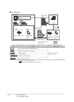
15.1 Data Storage Location
15 - 3
9
HANDLING OF PO
WER WI
RI
N
G
AND SWIT
CH
10
UTIL
ITY FUNC
TION
11
DI
SPLA
Y
A
N
D
OP
ERA
T
IO
N
SE
TTI
N
GS
12
COMMUNICA
TION
INTE
RF
A
C
E
SE
TT
IN
G
13
DE
BUG
14
S
E
LF CHECK
15
D
A
TA
CONTROL
16
IN
ST
ALLA
TI
ON OF
COREOS,
B
O
OT
OS A
ND
ST
ANDA
RD MONI
TO
R OS
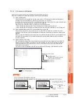
15.1.2 OS version confirmation
Confirm the OS version carefully when install BootOS and standard monitor OS.
When OS is installed, GOT checks and compares the OS version automatically.
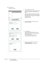
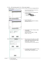
(1) When install BootOS
When the BootOS to be installed has the older major version, GOT displays the installation disapproving
message to cancel the installation so that the older version may not be written.
(Even when the version of the BootOS to be installed has the same or later version, the version information and
the dialog box for selecting continue/not continue will be displayed.)
Depending on the Installation method, the dialog box to be displayed varies.
• When installing from the standard CF card, the dialog box is displayed by the main unit.
• When installing from GT Designer3 via USB or Ethernet, the dialog box is displayed by the GT Designer3.
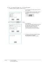
(2) When install standard monitor OS, communication driver, option OS
When standard monitor OS, communication driver, or option OS has already been installed, the version
information of the OS which has been installed and the dialog box for selecting continue/not continue will be
displayed.
Moreover, when the different versions will coexist among all OSs (standard monitor OS, communication driver,
and option OS) by installing OS, the installation disapproving dialog will be displayed and the installation
process is canceled.
(3) When download project data
GOT automatically compares the version between the project data to be downloaded and the installed OS.
When the versions are different, the dialog box confirming whether to install the OS together is displayed.
When downloading the project data from the CF card or USB memory, storing the project data and OS
beforehand is recommended.
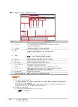
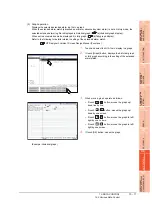
The version of each OS installed in the GOT can be confirmed by [Property] of [OS information] screen.
Refer to the following for details of the screen display operation.
POINT
POINT
POINT
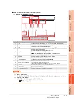
Version confirmation of BootOS by rating plate
Confirm the version of BootOS installed in the GOT at product shipment by rating plate of GOT rear face.
Explanation of OS version
01.00.00.A
BootOS version
(Appears only when the property
of the BootOS is displayed.)
Minor version
Major version
MODEL
MAC. ADD. 12. 34. 56. 78 .90. 12
GRAPHIC OPERATION TERMINAL
S/N
GT1665HS-VTBD
09Z0003
BootOS
Version
AA G
IN 20. 4 26. 4VDC POWER 11. 6W MAX
MITSUBISHI ELECTRIC CORPORATION
MADE IN JAPAN
AA
MODEL
MAC. ADD. 12. 34. 56. 78 .90. 12
GRAPHIC OPERATION TERMINAL
S/N
GT1665HS-VTBD
09Z0003
BootOS
Version
HD G
IN 20. 4 26. 4VDC POWER 11. 6W MAX
MITSUBISHI ELECTRIC CORPORATION
MADE IN JAPAN
HD
When the Boot OS version is 2 digits,
only the lower digit is printed.
Example H/W version: H
Boot OS version: AD
Rating plate: HD
Summary of Contents for GT16
Page 1: ......
Page 2: ......
Page 46: ...1 4 1 OVERVIEW 1 1 Features ...
Page 54: ...2 8 2 SYSTEM CONFIGURATION 2 2 System Equipment ...
Page 60: ...3 6 3 SPECIFICATIONS 3 4 Battery specifications ...
Page 72: ...5 8 5 UL cUL STANDARDS AND EMC DIRECTIVE 5 2 EMC Directive ...
Page 102: ...6 30 6 OPTION 6 7 Connector Conversion Box ...
Page 106: ...7 4 7 INSTALLATION 7 1 Installing Procedure ...
Page 110: ...8 4 8 COMMUNICATION CABLE 8 1 Overview of Communication Cable ...
Page 130: ...9 20 9 HANDLING OF POWER WIRING AND SWITCH 9 4 Switch Wiring ...
Page 142: ...10 12 10 UTILITY FUNCTION 10 3 Utility Display ...
Page 184: ...11 42 11 DISPLAY AND OPERATION SETTINGS GOT SET UP 11 4 Maintenance Function ...
Page 202: ...12 18 12 COMMUNICATION INTERFACE SETTING COMMUNICATION SETTING 12 3 Ethernet Setting ...
Page 226: ...13 24 13 DEBUG 13 3 Memory Data Control ...
Page 248: ...14 22 14 SELF CHECK 14 2 Batch Self Check ...
Page 350: ...15 102 15 DATA CONTROL 15 3 OS Project Information ...
Page 410: ...19 22 19 TROUBLESHOOTING 19 2 Error Message and System Alarm ...
Page 418: ...App 8 APPENDICES Appendix 3 Transportation Precautions ...
Page 422: ...REVISIONS 4 ...
Page 425: ......
Page 426: ......
Page 427: ......
Page 428: ......
Page 470: ......
Page 510: ...21 22 21 COMPUTER LINK CONNECTION 21 6 Precautions ...
Page 568: ...22 58 22 ETHERNET CONNECTION 22 5 Precautions ...
Page 584: ......
Page 626: ...25 14 25 SERVO AMPLIFIER CONNECTION 25 7 Precautions ...
Page 632: ...26 6 26 ROBOT CONTROLLER CONNECTION 26 6 Precautions ...
Page 647: ...MULTIPLE GOT CONNECTIONS 29 GOT MULTI DROP CONNECTION 29 1 ...
Page 648: ......
Page 659: ...MULTI CHANNEL FUNCTION 30 MULTI CHANNEL FUNCTION 30 1 ...
Page 660: ......
Page 675: ...FA TRANSPARENT FUNCTION 31 FA TRANSPARENT FUNCTION 31 1 ...
Page 676: ......
Page 742: ...31 66 31 FA TRANSPARENT FUNCTION 31 7 Precautions ...
Page 744: ......
Page 766: ...32 22 32 CONNECTION TO IAI ROBOT CONTROLLER 32 7 Precautions ...
Page 802: ...34 10 34 CONNECTION TO OMRON TEMPERATURE CONTROLLER 34 7 Precautions ...
Page 834: ...36 18 36 CONNECTION TO KOYO EI PLC 36 6 Device Range that Can Be Set ...
Page 858: ...38 12 38 CONNECTION TO SHARP PLC 38 6 Device Range that Can Be Set ...
Page 868: ...39 10 39 CONNECTION TO SHINKO TECHNOS INDICATING CONTROLLER 39 7 Precautions ...
Page 902: ...42 6 42 CONNECTION TO TOSHIBA MACHINE PLC 42 6 Device Range that Can Be Set ...
Page 908: ...43 6 43 CONNECTION TO PANASONIC SERVO AMPLIFIER 43 7 Precautions ...
Page 970: ...48 12 48 CONNECTION TO FUJI TEMPERATURE CONTROLLER 48 7 Precautions ...
Page 1052: ...52 26 52 CONNECTION TO AZBIL CONTROL EQUIPMENT 52 7 Precautions ...
Page 1102: ...55 14 55 CONNECTION TO GE PLC 55 7 Precautions ...
Page 1114: ...57 4 57 CONNECTION TO SICK SAFETY CONTROLLER 57 5 Device Range that Can Be Set ...
Page 1128: ...59 2 59 CONNECTION TO HIRATA CORPORATION HNC CONTROLLER ...
Page 1130: ...60 2 60 CONNECTION TO MURATEC CONTROLLER ...
Page 1132: ......
Page 1270: ...62 68 62 MICROCOMPUTER CONNECTION ETHERNET 62 8 Precautions ...
Page 1271: ...MODBUS CONNECTIONS 63 MODBUS R RTU CONNECTION 63 1 64 MODBUS R TCP CONNECTION 64 1 ...
Page 1272: ......
Page 1292: ...64 12 64 MODBUS R TCP CONNECTION 64 7 Precautions ...
Page 1293: ...CONNECTIONS TO PERIPHERAL EQUIPMENT 65 VNC R SERVER CONNECTION 65 1 ...
Page 1294: ......
Page 1298: ...65 4 65 VNC R SERVER CONNECTION 65 4 Setting in Personal Computer ...
Page 1302: ...REVISIONS 4 ...
Page 1305: ......
Page 1306: ......


