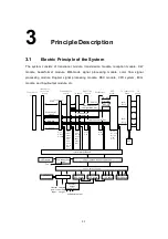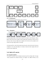
Principle Description
3-13
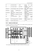
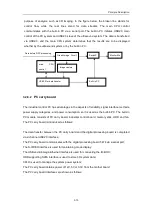
COM 1
PARALLEL
TO DVD RW (S-VIDEO IN, S-VIDEO OUT,
AUDIO IN, AUDIO OUT, SERIAL PORT)
ETHERNET 1/2
RESET
TO monitor (VGA, AUDIO-PW OUT)
VIDEO OUT
REMOTE 1
IO connecting board
Hard-wired
Hard-wired
TO CD-RW (IDE)
USB 1/2
S-VIDEO IN 1
AUDIO IN 1
S-VIDEO OUT 1
RGB OUT 1
KEYBOARD
DVD
CD RW
TOUCHSCREEN
IO interface board
HDD
AUDIO OUT 1
DSP
board
VIDEO IN 1
TO TOUCHSCREEN (SERIAL PORT, VGA)
TO VCR (S-VIDEO IN, S-VIDEO OUT,
AUDIO IN, AUDIO OUT, SERIAL PORT)
TO B/W VIDEO PRINTER (VIDEO OUT, REMOTE 1)
VGA OUT 1
VGA IN
RGB IN
IO adapter board
Hard-wired
Note: other modules are in the broken lines
LCD
LCD
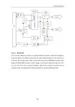
3.2.10 ECG module
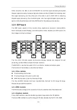
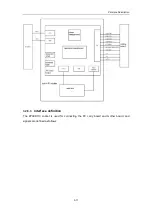
The ECG module is designed for monitoring of ECG signals and display of ECG waveforms,
which serve as reference of ultrasound images. The ECG module can synchronously trigger
display of 2-D images and color flow images. After the ECG signal is amplified, filtered and
sampled, through the RS232 serial port, the signal is sent to the DSC module; at the same
time the R-wave is detected, and the detected ECG-triggering signal is sent to the system
controllers through interrupt, to start the scan transmission. The ECG module communicates
with the main CPU system through the RS232 serial port.
The ECG signal can be inputted to the system, through an interface compatible with Mindray’s
monitoring products.
Summary of Contents for DC-6
Page 1: ...DC 6 DC 6T DC 6Vet Diagnostic Ultrasound System Service Manual...
Page 2: ......
Page 20: ...2 1 2 System Overview 2 1 System Appearance 2 1 1 Complete System with CRT Monitor...
Page 23: ...System Overview 2 4 2 2 LCD Monitor...
Page 26: ...System Overview 2 7 2 2 3 Lever of upper support arm...
Page 66: ...4 1 4 System Structure and Assembly Disassembly 4 1 Exploded View of Complete System...
Page 101: ...System Structure and Assembly Disassembly 4 36 Power boards Card detacher...
Page 191: ...P N 2105 20 40473 V10 0...


