Principle Description
3-25
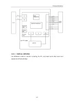
FORWARD
transformer
input
filter
circuit
+5V
power
board
PWM
control
390Vdc
VDD
magamp
adjustment
1
rectifier
filter
overcurre
nt & over-
voltage
detection
magamp
adjustment
2
rectifier
filter
ocp/ovp signal
rectifier
filter
optocoupler
isolation
feedback
OVP&
OVP
OTP
power
motherboard
-12V output
-5V output
+12V output
PFL signal
3.3.2.5
PHV board
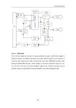
After the 12V input voltage enters the PHV, it passes the FLYBACK converter to generate two
groups of positive and negative high voltages. After the 12V input voltage passes the
BOOST converters and BUCK-BOOST converters, PHV1, PHV3, PHV2 and PHV4 are
outputted.
The control IC of the FLYBACK converter is UC3843 made by ONSEMI, and the main
switching tube is IRF3710 made by IR (100V/60A). The control IC o f the BOOST converter is
TL594 made by ONSEMI, and the switching tube is IRF52N15DPBF made by IR (150V/60A).
The control IC of the BUCK-BOOST converter is MAX1847 made by MAXIM, and the
switching tube is IRF6215PBF made by IR (150V/13A). The output voltage values have linear
relation with the programmable voltages. When the programmable voltages vary within the
range of 0 and 4V, the absolute values of the output voltages vary within the range of 5 and
80V.
Summary of Contents for DC-6
Page 1: ...DC 6 DC 6T DC 6Vet Diagnostic Ultrasound System Service Manual...
Page 2: ......
Page 20: ...2 1 2 System Overview 2 1 System Appearance 2 1 1 Complete System with CRT Monitor...
Page 23: ...System Overview 2 4 2 2 LCD Monitor...
Page 26: ...System Overview 2 7 2 2 3 Lever of upper support arm...
Page 66: ...4 1 4 System Structure and Assembly Disassembly 4 1 Exploded View of Complete System...
Page 101: ...System Structure and Assembly Disassembly 4 36 Power boards Card detacher...
Page 191: ...P N 2105 20 40473 V10 0...

