System Structure and Assembly/Disassembly
4-37
4.3.15 Remove built-in PC module
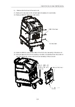
a) Repeat section 4.3.14.1 to push down the brake to lock up the casters.
b) Repeat section 4.3.14.2 to remove screws and rear cover.
c) Repeat steps a and b in section 4.3.14.3 to remove wires of IO panel, and to remove IO
panel; remove the network cables and USB wire of PC module and IO panel.
d) Remove four M4x8 screws fixing built-in PC module, two screws above and two below;
grasp the handle and take the PC module out.
M4X8 screws
Summary of Contents for DC-6
Page 1: ...DC 6 DC 6T DC 6Vet Diagnostic Ultrasound System Service Manual...
Page 2: ......
Page 20: ...2 1 2 System Overview 2 1 System Appearance 2 1 1 Complete System with CRT Monitor...
Page 23: ...System Overview 2 4 2 2 LCD Monitor...
Page 26: ...System Overview 2 7 2 2 3 Lever of upper support arm...
Page 66: ...4 1 4 System Structure and Assembly Disassembly 4 1 Exploded View of Complete System...
Page 101: ...System Structure and Assembly Disassembly 4 36 Power boards Card detacher...
Page 191: ...P N 2105 20 40473 V10 0...


