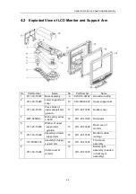
System Structure and Assembly/Disassembly
4-7
Adjust the LCD monitor after changing or replacing the main board:
a)
Follow step 1, 2 and 3 in section 7.2.3.1 to enter the System Maintenance Menu
and select the Monitor Test item.
b)
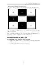
Press the left direction key on the minor keyboard to display the following screen.
Press <1> and <4> buttons and hold for at least 3s until the blue menu displays on
the screen, select “autojust” via button <1> and <2>, and press <4> to confirm; the image
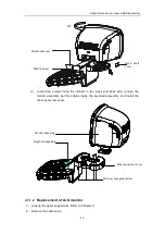
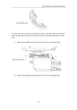
Tilt the monitor to the position as shown in the
figure, and hold it by two sides and lift it in the
direction of F, until it is disconnected.
Summary of Contents for DC-6
Page 1: ...DC 6 DC 6T DC 6Vet Diagnostic Ultrasound System Service Manual...
Page 2: ......
Page 20: ...2 1 2 System Overview 2 1 System Appearance 2 1 1 Complete System with CRT Monitor...
Page 23: ...System Overview 2 4 2 2 LCD Monitor...
Page 26: ...System Overview 2 7 2 2 3 Lever of upper support arm...
Page 66: ...4 1 4 System Structure and Assembly Disassembly 4 1 Exploded View of Complete System...
Page 101: ...System Structure and Assembly Disassembly 4 36 Power boards Card detacher...
Page 191: ...P N 2105 20 40473 V10 0...


