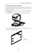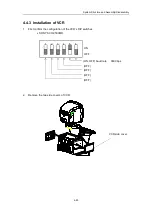
System Structure and Assembly/Disassembly
4-66
6.
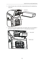
Connect the power cable and signal cable (to alternative of S VIDEO connectors). The
audio IN/OUT and S VIDEO IN/OUT cables are integrated into one strand of cables for
the VCR module.
7.
Install the right cover, but store the left cover properly.
Audio input
S VIDEO input
Audio output
S VIDEO output
Power socket
VCR serial port
Summary of Contents for DC-6
Page 1: ...DC 6 DC 6T DC 6Vet Diagnostic Ultrasound System Service Manual...
Page 2: ......
Page 20: ...2 1 2 System Overview 2 1 System Appearance 2 1 1 Complete System with CRT Monitor...
Page 23: ...System Overview 2 4 2 2 LCD Monitor...
Page 26: ...System Overview 2 7 2 2 3 Lever of upper support arm...
Page 66: ...4 1 4 System Structure and Assembly Disassembly 4 1 Exploded View of Complete System...
Page 101: ...System Structure and Assembly Disassembly 4 36 Power boards Card detacher...
Page 191: ...P N 2105 20 40473 V10 0...

