Principle Description
3-16
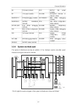
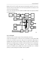
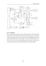
The block diagram of the detection board is shown as follows:
power
output
module
HPV1
-HPV1
HPV2
-HPV2
voltage
divider
voltage
divider
voltage
divider
voltage
divider
follow
follow
backward
backward
lowpass
lowpass
lowpass
lowpass
AD7928
+A5V
-D12V
+D12V
-A100V
voltage
divider
voltage
divider
voltage
divider
voltage
divider
backward
backward
lowpass
lowpass
lowpass
lowpass
Atmega
64L
voltage
divider
lowpass
+D5V
ADT7516
CON1
CON2
CON3
CON4
S
P
I
SPI
voltage
divider
lowpass
+D3P3V
clock
JTAG
SPI
download
interface
232
Max6066
VREF
MAX3243
TTL
CONNECTOR
POWER
+D5V
-A5V
+5V
A5V
REF3040
ADT7516_VREF
voltage
divider
+A100V
lowpass
-A5V
3.2.13 CRT monitor
The CRT monitor is used to convert electric signal, transmitted from the main board, to
high-speed electrons for impacting fluorescent screen, thus generating light signal to make
images seen on the screen. The external indicator of the CRT is designed to judge if the
monitor works normally. Generally if there is synchronous signal, this indicator is green;
otherwise it is yellow.
Summary of Contents for DC-6
Page 1: ...DC 6 DC 6T DC 6Vet Diagnostic Ultrasound System Service Manual...
Page 2: ......
Page 20: ...2 1 2 System Overview 2 1 System Appearance 2 1 1 Complete System with CRT Monitor...
Page 23: ...System Overview 2 4 2 2 LCD Monitor...
Page 26: ...System Overview 2 7 2 2 3 Lever of upper support arm...
Page 66: ...4 1 4 System Structure and Assembly Disassembly 4 1 Exploded View of Complete System...
Page 101: ...System Structure and Assembly Disassembly 4 36 Power boards Card detacher...
Page 191: ...P N 2105 20 40473 V10 0...


