System Overview
2-18
2.7
Symbols
This system uses the symbols listed in the following table, and their meanings are
explained as well. Refer to “Safety Precautions” for safety symbols.
Symbol
Meaning
Type-BF device
!
Refer to relevant content in the Operation Manual, to avoid
safety accidents
Dangerous voltage
AC (alternate current)
Functional earth
Equipotentiality
Protective earth
Breaker ON/OFF
Power ON/OFF
Footswitch
Transducer socket
Network port
Parallel port
Serial port
S-VIDEO signal interface
VIDEO signal interface
VGA signal
RGB signal
External signal input
Remote control port
USB
Summary of Contents for DC-6
Page 1: ...DC 6 DC 6T DC 6Vet Diagnostic Ultrasound System Service Manual...
Page 2: ......
Page 20: ...2 1 2 System Overview 2 1 System Appearance 2 1 1 Complete System with CRT Monitor...
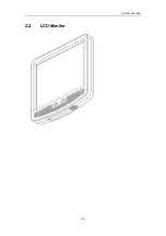
Page 23: ...System Overview 2 4 2 2 LCD Monitor...
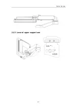
Page 26: ...System Overview 2 7 2 2 3 Lever of upper support arm...
Page 66: ...4 1 4 System Structure and Assembly Disassembly 4 1 Exploded View of Complete System...
Page 101: ...System Structure and Assembly Disassembly 4 36 Power boards Card detacher...
Page 191: ...P N 2105 20 40473 V10 0...

