System Structure and Assembly/Disassembly
4-61
5.
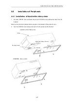
Use the screws to fix the printer on the fixing bracket. Note that the side which has
holes shall face to the front of the printer.
6.
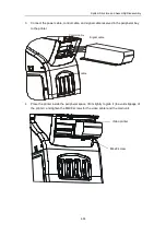
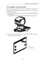
Place the fixing bracket on the mounting bracket, and push it inside the mounting
bracket. Note the guides of the fixing bracket and mounting bracket shall match well
and be fixed with screws.
M3X8 screw
M3X8 screw
Fixing bracket
Summary of Contents for DC-6
Page 1: ...DC 6 DC 6T DC 6Vet Diagnostic Ultrasound System Service Manual...
Page 2: ......
Page 20: ...2 1 2 System Overview 2 1 System Appearance 2 1 1 Complete System with CRT Monitor...
Page 23: ...System Overview 2 4 2 2 LCD Monitor...
Page 26: ...System Overview 2 7 2 2 3 Lever of upper support arm...
Page 66: ...4 1 4 System Structure and Assembly Disassembly 4 1 Exploded View of Complete System...
Page 101: ...System Structure and Assembly Disassembly 4 36 Power boards Card detacher...
Page 191: ...P N 2105 20 40473 V10 0...

