Principle Description
3-3
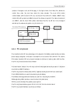
represents A, B or C) signal to select the corresponding transducer. Since the system may
read multiple transducer ID codes simultaneously, the system software will select the
corresponding transducer based on the current exam.
When transducers are disconnected or connected, the interrupt signal will be automatically
generated to notify the system software, so that the system software can obtain the current
status of transducer connection and provide the prompt message accordingly.
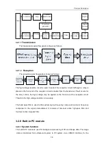
3.2.2 Transmission board
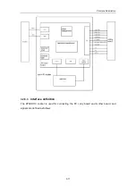
The block diagram of the transmission board is shown as follows:
The transmission board is designed for generation of high-voltage pulse and transmission
sequence. The transmission circuit consists of two parts: transmission sequence and
transmission drive. The transmission sequence circuit generates low-voltage transmission
pulse, which passes the transmission drive circuit and is converted to high-voltage pulse. The
transmission board is provided with four programmable transmission voltages by the power
supply, so that the board can generate different transmission waveforms depending on the
needs of the system.
3.2.3 Amplifier board
The block diagram of the amplifier board is shown as follows:
The amplifier board is designed for voltage-controlled gain amplification of small signal echo.
Summary of Contents for DC-6
Page 1: ...DC 6 DC 6T DC 6Vet Diagnostic Ultrasound System Service Manual...
Page 2: ......
Page 20: ...2 1 2 System Overview 2 1 System Appearance 2 1 1 Complete System with CRT Monitor...
Page 23: ...System Overview 2 4 2 2 LCD Monitor...
Page 26: ...System Overview 2 7 2 2 3 Lever of upper support arm...
Page 66: ...4 1 4 System Structure and Assembly Disassembly 4 1 Exploded View of Complete System...
Page 101: ...System Structure and Assembly Disassembly 4 36 Power boards Card detacher...
Page 191: ...P N 2105 20 40473 V10 0...


