System Structure and Assembly/Disassembly
4-31
4.3.14.1
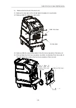
Press down the brakes of the casters
Note: Brake the system immediately when it isn’t necessary to move it.
4.3.14.2
Remove the screw caps, screws and rear cover
a)
Remove 10 screw caps of the rear cover.
b)
Remove 13 M4×8 screws connecting the rear cover and the main unit housing.
c)
Push down the rear cover assembly, remove the handle of the main unit, and
remove the rear cover assembly.
Press down the
brakes.
Summary of Contents for DC-6
Page 1: ...DC 6 DC 6T DC 6Vet Diagnostic Ultrasound System Service Manual...
Page 2: ......
Page 20: ...2 1 2 System Overview 2 1 System Appearance 2 1 1 Complete System with CRT Monitor...
Page 23: ...System Overview 2 4 2 2 LCD Monitor...
Page 26: ...System Overview 2 7 2 2 3 Lever of upper support arm...
Page 66: ...4 1 4 System Structure and Assembly Disassembly 4 1 Exploded View of Complete System...
Page 101: ...System Structure and Assembly Disassembly 4 36 Power boards Card detacher...
Page 191: ...P N 2105 20 40473 V10 0...

