Principle Description
3-20
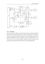
board, adapter board of auxiliary output, LED board, adapter board of fans, power
motherboard and detection board of power output.
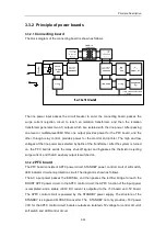
The AC line power passes the circuit breaker to enter the connecting board, and then, through
the isolation transformer, two isolated outputs are obtained. After filtered, one output serves
as AC auxiliary output for the monitor and printers, the other passes the power motherboard
to become the input power for the PFC board. After entering the PFC board, the power is
converted to a stable 390V high-voltage DC output through the BOOST PFC, and then
provided for the +5V board and -5V board to finally 5V, +3.3V, -5V, 12V and -12V. The
12V serves as the input power of the PHV board, and it passes the FLYBACK converter in the
PHV board to output ±100V voltages; four programmable voltages are obtained through the
BOOST converter and BUCK-BOOST converter.
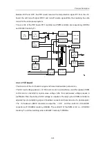
After passing the power motherboard, the outputs of the power system are connected to the
detection board of power output for filtering and monitoring. After the programmable voltages
are detected, they are outputted to the main unit for supplying power for relevant hardware
circuits. The outputs of the power system, after passing the fan adapter board, are connected
to the LED board. The LED board indicates the statuses of the outputs.
Summary of Contents for DC-6
Page 1: ...DC 6 DC 6T DC 6Vet Diagnostic Ultrasound System Service Manual...
Page 2: ......
Page 20: ...2 1 2 System Overview 2 1 System Appearance 2 1 1 Complete System with CRT Monitor...
Page 23: ...System Overview 2 4 2 2 LCD Monitor...
Page 26: ...System Overview 2 7 2 2 3 Lever of upper support arm...
Page 66: ...4 1 4 System Structure and Assembly Disassembly 4 1 Exploded View of Complete System...
Page 101: ...System Structure and Assembly Disassembly 4 36 Power boards Card detacher...
Page 191: ...P N 2105 20 40473 V10 0...


