VI
6
.
.
.
.
No waterproof device is applied to this equipment. Do not use this
equipment in any place with the possibility of water ingress. There
is risk of electric shock if any water is sprayed on or into the
equipment. If carelessly spray any water onto the equipment,
contact the Mindray sales office, customer service department or
representative.
7
.
.
.
.
Use the transducer carefully. In case that the body contacts the
scratched transducer surface, immediately stop using the
transducer and contact the Mindray sales office, customer service
department or representative. There is risk of electric shock if using
the scratched transducer.
8
.
.
.
.
Be careful not to let the patient contact the live parts of the
ultrasound equipment or other devices, such as signal I/O ports. If
the ultrasound equipment is defective, there is risk of electric
shock.
9. Do not use the transducers other than those specified by Mindray.
Otherwise, the equipment and the transducer may be damaged,
causing an accident such as a fire in the worst case.
10.
Do not subject the transducers to knocks. Use of defective
transducers may cause an electric shock.
11. Do not open the shell or front panel. If you open the shell when the
system is powered on, there may be a short circuit or electric
shock.
12. Do not use this system with using equipment at the same time such
as an electrosurgical unit, high-frequency therapy equipment, or a
defibrillator, etc. otherwise it may result in electric shock to the
patient.
13. Use only the ECG leads provided with the ECG module, otherwise it
may result in electric shock.
14. If this system needs to be moved, please hold the handle. If other
parts of the system are held, it may cause damage due to the
abnormal force. Do not push the system from the left/right side;
otherwise it may be toppled over.
Summary of Contents for DC-6
Page 1: ...DC 6 DC 6T DC 6Vet Diagnostic Ultrasound System Service Manual...
Page 2: ......
Page 20: ...2 1 2 System Overview 2 1 System Appearance 2 1 1 Complete System with CRT Monitor...
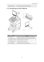
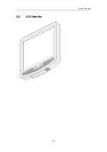
Page 23: ...System Overview 2 4 2 2 LCD Monitor...
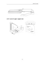
Page 26: ...System Overview 2 7 2 2 3 Lever of upper support arm...
Page 66: ...4 1 4 System Structure and Assembly Disassembly 4 1 Exploded View of Complete System...
Page 101: ...System Structure and Assembly Disassembly 4 36 Power boards Card detacher...
Page 191: ...P N 2105 20 40473 V10 0...


