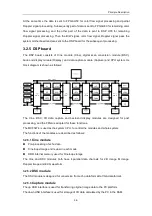
Principle Description
3-7
D2
5V power indicator
D30
ISP1161
test
output
indicator
D7
-5V power indicator
D31-D34
Connection indicator of
network control
D8,D14,D15
FPGA debugging indicator
D37,D39-D41
DSC
FPGA
debugging
indicator
D9,D10,D25
ISP1561
USBVBUS
indicator
D38
Cine FPGA configuration
status indicator
D11,D18,D36
Cine
FPGA
debugging
indicator
D42-D44
ISP1583
Suspending
status indicator
D12
DSC FPGA configuration
indicator
D45-D48
Capture FPGA debugging
status indicator
D13
12V power indicator
D49
Capture
FPGA
configuration
status
indicator
D17, D26
CPU debugging indicator
D50-D51
CPLD debugging status
indicator
D19-D24
ISP1561 status indicator
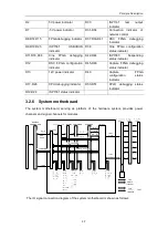
3.2.6 System motherboard
The system motherboard, serving as platform of the hardware system, provides power
channels and signal channels for modules.
The IO signal connection diagram of the system motherboard is shown as follows:
Summary of Contents for DC-6
Page 1: ...DC 6 DC 6T DC 6Vet Diagnostic Ultrasound System Service Manual...
Page 2: ......
Page 20: ...2 1 2 System Overview 2 1 System Appearance 2 1 1 Complete System with CRT Monitor...
Page 23: ...System Overview 2 4 2 2 LCD Monitor...
Page 26: ...System Overview 2 7 2 2 3 Lever of upper support arm...
Page 66: ...4 1 4 System Structure and Assembly Disassembly 4 1 Exploded View of Complete System...
Page 101: ...System Structure and Assembly Disassembly 4 36 Power boards Card detacher...
Page 191: ...P N 2105 20 40473 V10 0...

