System Structure and Assembly/Disassembly
4-24
b)
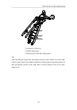
After the keyboard assembly ejects in position, as shown in the figure (seen from
the back surface), use two hands simultaneously to toggle the two plastic rods at the first
nodes of the slide tracks on the back surface of the keyboard assembly (squat down if
necessary), and slightly pull out the keyboard assembly; draw out the keyboard with the
first nodes of the sliding tracks.
①
②
Plastic rod
Plastic rod
Direction
of moving
Direction of moving
Keyboard assembly
Summary of Contents for DC-6
Page 1: ...DC 6 DC 6T DC 6Vet Diagnostic Ultrasound System Service Manual...
Page 2: ......
Page 20: ...2 1 2 System Overview 2 1 System Appearance 2 1 1 Complete System with CRT Monitor...
Page 23: ...System Overview 2 4 2 2 LCD Monitor...
Page 26: ...System Overview 2 7 2 2 3 Lever of upper support arm...
Page 66: ...4 1 4 System Structure and Assembly Disassembly 4 1 Exploded View of Complete System...
Page 101: ...System Structure and Assembly Disassembly 4 36 Power boards Card detacher...
Page 191: ...P N 2105 20 40473 V10 0...


