Principle Description
3-18
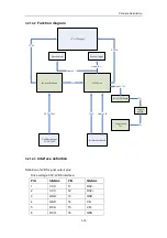
3.2.14.2
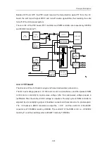
Function diagram
15" LCD panel
Inverter & Power
LCD drive
Light board
12v
Auxiliary output
AC 90-260V
IO interface board
Speaker(right)
Speaker(left)
Key OSD board
Toggle
switch
Audio R +/-
Audio L +/-
CCFL
LVDS
AC 90-260V
VGA
Audio L/R
Signal , 12v
12v
12v
12v
3.2.14.3
Interface definition
Definition of LVDS signal output pins:
Drive voltage 3.3V, LVDS interface.
PIN
SIGNAL
PIN
SIGNAL
1
VCC
11
RX2-
2
VCC
12
RX2+
3
GND
13
GND
4
GND
14
CK-
5
RX0-
15
CK+
6
RX0+
16
GND
Summary of Contents for DC-6
Page 1: ...DC 6 DC 6T DC 6Vet Diagnostic Ultrasound System Service Manual...
Page 2: ......
Page 20: ...2 1 2 System Overview 2 1 System Appearance 2 1 1 Complete System with CRT Monitor...
Page 23: ...System Overview 2 4 2 2 LCD Monitor...
Page 26: ...System Overview 2 7 2 2 3 Lever of upper support arm...
Page 66: ...4 1 4 System Structure and Assembly Disassembly 4 1 Exploded View of Complete System...
Page 101: ...System Structure and Assembly Disassembly 4 36 Power boards Card detacher...
Page 191: ...P N 2105 20 40473 V10 0...


