System Overview
2-8
2.3
I/O Panel
No
Symbol
Function
<1>
Used for system recovery
<2>, <3>
Ethernet interface (<2> is reserved for future
use; <3> can be used now.)
<4>
System reset
<5>
Serial port
<6>
Control port for color video printer
<7>, <8>
USB port (<8> is used for USB devices, while
<7> is for expansion.)
<9>,<10>
Used for VGA I/O
<11>,<12>
Used for RGB component video I/O
<13>,<14>
Used for separate video I/O
<15>,<16>
Used for composite video I/O
<17>,<18>
<19>,<20>
Used for stereo audio I/O
<1>
<9>
<13>
<17>
<2>
<5>
<10>
<14>
<18>
<3>
<6>
<11>
<15>
<19>
<4>
<7>
<12>
<16>
<20>
<8>
Summary of Contents for DC-6
Page 1: ...DC 6 DC 6T DC 6Vet Diagnostic Ultrasound System Service Manual...
Page 2: ......
Page 20: ...2 1 2 System Overview 2 1 System Appearance 2 1 1 Complete System with CRT Monitor...
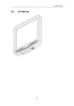
Page 23: ...System Overview 2 4 2 2 LCD Monitor...
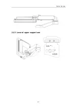
Page 26: ...System Overview 2 7 2 2 3 Lever of upper support arm...
Page 66: ...4 1 4 System Structure and Assembly Disassembly 4 1 Exploded View of Complete System...
Page 101: ...System Structure and Assembly Disassembly 4 36 Power boards Card detacher...
Page 191: ...P N 2105 20 40473 V10 0...

