Principle Description
3-23
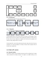
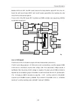
Besides OVP and OTP, the PFC board receives the fail protection signal PF from the +5V
board, the soft turn-off signal POFF and turn-off enable signal ENA, thus realizing the safe
turn-off of the entire power system.
The core ICs of the PFC board, PFC controller and PWM controller, are respectively UC3854
and 38HC43 made by TI.
EMI
FILTER
1
APFC
COUPLER
CIRCUIT
PHOTO
-
OVP
/
OTP
CIRCUIT
DIODE
BRIDGE
CONTROL
390Vout
PWM
CONTROL
CIRCUIT
REGULATOR
ON/OFF
LOGIC
LED
CONTROL
CIRCUIT
REGULATOR
CIRCUIT
ON/OFF
CONTROL
CIRCUIT
DC+
VDD
LED
ENA
SW
RY+
PF
POFF
+5V BOARD
-5V BOARD
3.3.2.3
+5V board
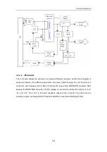
The structure of the +5V board is single-end forward active-clamp conversion.
The DC input voltage passes a LC filter and is sent to a transformer, and then passes PWM
control and is converted to square-wave voltage. After the square-wave voltage passes a
rectification filter, the 5V DC voltage is outputted. The duty cycle of PWM controller is
adjusted by error-amplifying signal of feedback network and transmission of a photocoupler.
The
+
5V passes a BUCK converter to output the
+
3.3V, and the control IC of the BUCK
converter is LTC1629EG made by LINEAR. The control IC of the PWM is U9, i.e., UCC2894
made by TI, and the switching tube is 2KS2611 made by TOSHIBA.
Summary of Contents for DC-6
Page 1: ...DC 6 DC 6T DC 6Vet Diagnostic Ultrasound System Service Manual...
Page 2: ......
Page 20: ...2 1 2 System Overview 2 1 System Appearance 2 1 1 Complete System with CRT Monitor...
Page 23: ...System Overview 2 4 2 2 LCD Monitor...
Page 26: ...System Overview 2 7 2 2 3 Lever of upper support arm...
Page 66: ...4 1 4 System Structure and Assembly Disassembly 4 1 Exploded View of Complete System...
Page 101: ...System Structure and Assembly Disassembly 4 36 Power boards Card detacher...
Page 191: ...P N 2105 20 40473 V10 0...

