Principle Description
3-12
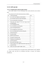
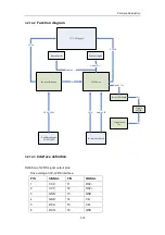
Interfaces between the PC carry board and IOBOX: 1 USB port, 1 network port.
3.2.9 IO module
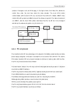
The IO module consists of IO connecting board, IO adapter board, and IO interface board.
The connection relation between these boards is shown as follows:
1.
One end of the IO connecting board is connected to the DSP board, and the other end is
connected to the IO adapter board; the standard 40PIN IDE HDD interface and 4PIN
power interface are provided, and the power socket for HDD cooling fan is reserved.
2.
One end of the IO adapter board is connected to the IO connecting board, and the other
end is connected to the IO interface board; the adapter board serves as an extension
board.
3.
The IO interface board is connected to the IO adapter board, and provides IO interfaces
and the power of the system; the IO interfaces are divided into internal IO (invisible for
the user) and external IO (visible for the user).
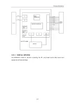
The block diagram of the IO module is shown as follows:
Model: 110Pin PC platform
PA
SIG.DES
PB
SIG.DES
PC
SIG.DES
PD
SIG.DES PE
SIG.DES
PA.1
GND
PB.1
DM-SIG
PC.1
DP-SIG
PD.1
GND
PE.1
VBUS-SIG
PA.2
GND
PB.2
DM-PC2
PC.2
DP-PC2
PD.2
GND
PE.2
VBUS-PC2
PA.3
VBUS-PC1
PB.3
DM-PC1
PC.3
DP-PC1
PD.3
GND
PE.3
GND
PA.4
PC-YIN
PB.4
PC-CIN
PC.4
GND
PD.4
GND
PE.4
GND
PA.5
PW-STS
PB.5
BOARD-DETECT PC.5
NC
PD.5
NC
PE.5
NC
PA.6
GND
PB.6
GND
PC.6
GND
PD.6
GND
PE.6
GND
PA.7
RXD-PC
PB.7
TXD-PC
PC.7
PS-DATA PD.7
PS-CLK
PE.7
/
PA.8
GND
PB.8
GND
PC.8
GND
PD.8
GND
PE.8
GND
PA.9
GND
PB.9
GND
PC.9
GND
PD.9
GND
PE.9
GND
PA.10
D+5
PB.10
D+5
PC.10
D+5
PD.10
D+5
PE.10
D+5
PA.11
D+5
PB.11
D+5
PC.11
D+5
PD.11
D+5
PE.11
D+5
PA.12
D+5
PB.12
D+5
PC.12
D+5
PD.12
D+5
PE.12
D+5
PA.13
GND
PB.13
GND
PC.13
GND
PD.13
GND
PE.13
GND
PA.14
GND
PB.14
GND
PC.14
GND
PD.14
GND
PE.14
GND
PA.15
D+3.3
PB.15
D+3.3
PC.15
D+3.3
PD.15
D+3.3
PE.15
D+3.3
PA.16
D+3.3
PB.16
D+3.3
PC.16
D+3.3
PD.16
D+3.3
PE.16
D+3.3
PA.17
GND
PB.17
GND
PC.17
GND
PD.17
GND
PE.17
GND
PA.18
A-5
PB.18
A-5
PC.18
A-5
PD.18
A-5
PE.18
A-5
PA.19
GND
PB.19
GND
PC.19
GND
PD.19
GND
PE.19
GND
PA.20
GND
PB.20
GND
PC.20
GND
PD.20
GND
PE.20
GND
PA.21
D+12
PB.21
D+12
PC.21
D+12
PD.21
D+12
PE.21
D+12
PA.22
D+12
PB.22
D+12
PC.22
D+12
PD.22
D+12
PE.22
D+12
Summary of Contents for DC-6
Page 1: ...DC 6 DC 6T DC 6Vet Diagnostic Ultrasound System Service Manual...
Page 2: ......
Page 20: ...2 1 2 System Overview 2 1 System Appearance 2 1 1 Complete System with CRT Monitor...
Page 23: ...System Overview 2 4 2 2 LCD Monitor...
Page 26: ...System Overview 2 7 2 2 3 Lever of upper support arm...
Page 66: ...4 1 4 System Structure and Assembly Disassembly 4 1 Exploded View of Complete System...
Page 101: ...System Structure and Assembly Disassembly 4 36 Power boards Card detacher...
Page 191: ...P N 2105 20 40473 V10 0...


