System Overview
2-2
No
Name
Function
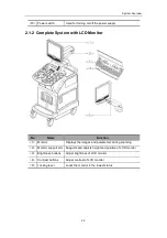
<1> Monitor
Displays the images and parameters during scanning
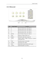
<2> Minor panel
Human-machine interface, operation control
<3> Main panel
Human-machine interface, operation control
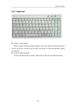
<4> Keyboard
Human-machine interface, operation control
<5> DVD-R/W
Rewritable CD drive
<6> Space for placing
video printer
Used for placing B/W video printer
<7> Transducer socket
Interface connecting transducers and the main unit
There are 3 active sockets and one dummy socket
<8> Casters
Used for fixing or moving the system
<9> Handle
Used for pushing the system
<10> Transducer holder
Used for placing transducers temporarily
<11> ECG panel
Used for connecting the ECG cable and footswitch, etc.
<12> Table
for
placing
color printer
Used for placing color video printer
<13> I/O panel
Interface panel for input and output signals
<14> Power panel
Electrical interface panel
<15> USB interface
Used for USB devices
<16> MIC interface
Used for connecting a microphone
<17> Space for placing
VCR
Used for placing VCR
Summary of Contents for DC-6
Page 1: ...DC 6 DC 6T DC 6Vet Diagnostic Ultrasound System Service Manual...
Page 2: ......
Page 20: ...2 1 2 System Overview 2 1 System Appearance 2 1 1 Complete System with CRT Monitor...
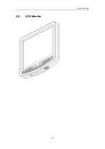
Page 23: ...System Overview 2 4 2 2 LCD Monitor...
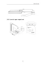
Page 26: ...System Overview 2 7 2 2 3 Lever of upper support arm...
Page 66: ...4 1 4 System Structure and Assembly Disassembly 4 1 Exploded View of Complete System...
Page 101: ...System Structure and Assembly Disassembly 4 36 Power boards Card detacher...
Page 191: ...P N 2105 20 40473 V10 0...


