background image

Service & Installation Instructions

P-273-5-WE
819-0529

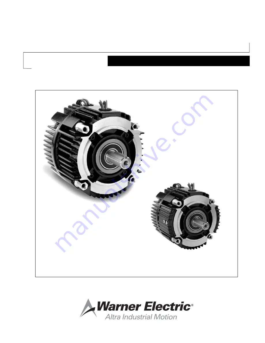
Electro-Module EM-50, EM-100, EM-180

Electrically Released Permanent Magnet Brake Module

EM-50-20FBB, EM-100-20FBB, EM-180-20FBB

EM-50-20FBC, EM-100-20FBC, EM-180-20FBC

Vented

Enclosed Version Optional

Summary of Contents for EM-50

Page 1: ...ructions P 273 5 WE 819 0529 Electro Module EM 50 EM 100 EM 180 Electrically Released Permanent Magnet Brake Module EM 50 20FBB EM 100 20FBB EM 180 20FBB EM 50 20FBC EM 100 20FBC EM 180 20FBC Vented E...

Page 2: ...d 10 40 Electro Modules are designed to mount to the face of a C frame motor as noted in Table 1 Corresponding NEMA Frame Sizes EM Old New Shaft C Face Size NEMA NEMA Dia Pilot Dia 50 56 C 48 Y 5 8 4...

Page 3: ...H I K Electro Module Fail Safe Brake only C Face Motor 20 FBB D J H I Motor Mount Electro Module Brake on C Face Motor 20M D C E H I K Motor Mount Electro Module Fail Safe Brake on C Face Motor 20FBB...

Page 4: ...oles of the brake module 20 or 20FBC or if clutch only the module 40 to the pilot and mounting holes of the clutch module 10 The wire exit orientation should match Secure the modules to the motor with...

Page 5: ...4 tie bolts provided Tighten the four 4 bolts alternately to ensure even alignment of the modules Tighten them to 30 35 foot pounds Figure 4 Section C Adjusting the Airgap For new installations it is...

Page 6: ...tate as well 3 Alternately repeat steps 1 2 to ensure that the airgap between the armature and its mating surface is about 1 32 inch and the armature remains square to its mating surface If the armatu...

Page 7: ...ng the Motor Mount Bracket 10 20 10 20FBC 10 40 20 20FBB A Motor Mount Bracket can be installed on the output end of a module 10 20 or 10 20FBC 20 20 FBB or 10 40 to provide a foot mounting for the co...

Page 8: ...module to the reducer flange The four 4 bolts that are required 3 8 16UNC2A are typically provided with the reducer Tighten to 18 22 foot pounds of torque Section H Mounting on the Input and Output S...

Page 9: ...tric Conduit Box Kit part number 5370 101 042 can be purchased separately The Conduit Box provides two conduit connection holes for standard 1 2 inch conduit connectors Note If you have a clutch brake...

Page 10: ...utch armature airgap should be adjusted at this time per section C The brake must be energized released during the clutch airgap adjustment so the output shaft can be rotated by hand Section K Burnish...

Page 11: ...le Options Vented Warner Electric Electro Module and base assemblies can be oriented as necessary to keep contaminates from entering the open housing vents If an Enclosed Electro Module 10 20 10 40 20...

Page 12: ...sembled as the final step Notes Visit Warner Electric s website at www warnerelectric com for dimensional drawings weights inertia s and a complete offering of our products including clutches brakes a...

Page 13: ...Warner Electric 800 825 9050 P 273 5 WE 819 0529 13 NOTES...

Page 14: ...nty lasts so the above limitation may not apply to you Warner Electric LLC s obligation under this warranty is limited to the repair or replacement of the defective product and in no event shall Warne...

Reviews: