background image

14.3.4  Batteries. 

The batteries of the BALTO COMPACT 4000 are located in the Main Unit. The batteries of the BALTO Modular are 
located in the Support Carriage. 

Replacing the batteries of the BALTO Compact 4000 can only be performed by a Megger Service Centre. It is 
sufficient to ship the Main Unit.

The lifetime of the batteries depends on various factors such as usage, grades of depletion, temperatures, etc. When 
it is noticed that current injections are deteriorating, it is necessary to check and replace the batteries. 

Although it is recommended that the replacement of batteries of the BALTO Modular is done in a Megger Service 
Centre, it can be done by trained personnel. The procedure is as follows :


„

Remove the Support Carriage from mains power.


„

Remove the DC Current Generators. 


„

Remove the lever from the Emergency Stop Device. 


„

Remove the Support Carriage cover plate. 


„

Remove a connection from every battery row. 

NOTE : 

Care must be taken and proper tools must be used to avoid creating short circuits when 

manipulating the batteries.


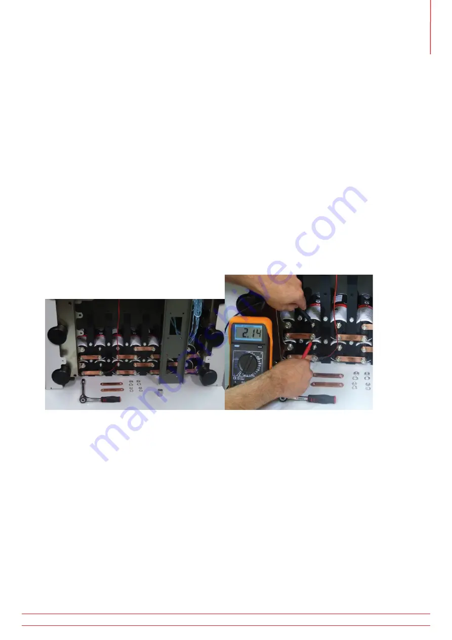
Fig 51: 

Support Carriage: Checking the batteries. 


„

Check the voltage of every battery cell. A healthy cell will have a voltage of at least 2.0 VDC.

Battery tightening torque: 3.5 N·m (2.6 lbf·ft)

Before reconnecting a battery row, ensure the battery row voltage matches the ultracapacitor voltage. If the 
ultracapacitor voltage is lower (e.g. after replacing battery cells), the system should be connected to mains power 
briefly to charge the ultracapacitor voltage to the battery row voltage, to avoid sparks during reconnection.

It is recommended to charge the BALTO System for at least 48 hours a week, even when not in active use. 
Regular charging will keep the batteries in good health and increases lifespan. 
Store the system at appropriate storage temperatures. 

14.4   Power Connectors. 

The Power Junction Connectors, as well as the power connections on the test object, must be kept clean.

To clean off dust, use compressed air. Do not use harsh chemicals for cleaning.

Abrasive fleece can be used for cleaning the Power Connector contact surface.

www.megger.com


153

Maintenance 

Summary of Contents for BALTO Compact 4000

Page 1: ...DC High Current Circuit Breaker Tester BALTO Modular 4 000A to 40 000A BALTO Compact 4 000 A User Guide...

Page 2: ...r the specification of its products from time to time without notice Although every effort is made to ensure the accuracy of the information contained within this document it is not warranted or repre...

Page 3: ...imited described in this user guide is in compliance with Directives 2014 30 EU and 2014 35 EU where they apply The full text of Megger Instruments EU declarations of conformity are available at the f...

Page 4: ...ng modes 8 4 BALTO Modular hardware 9 4 1 Support Carriage 10 4 2 Emergency Stop Device 12 4 3 Supply Fuses and Charge Connector 13 4 4 Power Connections 13 4 5 Sockets for the DC Current Generators 1...

Page 5: ...drop 34 9 2 Software structure 35 9 2 1 General information 35 9 2 2 Background 37 9 2 3 Message management 39 9 3 Booting up the BALTO System 39 9 3 1 Start procedure 39 9 4 Operating conditions 42...

Page 6: ...n 107 11 5 Main Menu 108 11 5 1 Tuning the BALTO PROTECTION TEST module for a specific relay 109 11 6 Testmodes 113 11 6 1 Manual Mode 114 11 6 2 Advanced Mode 117 12 Calibration 122 12 1 Preparations...

Page 7: ...downloading 150 14 Maintenance 152 14 1 Junction Connectors 152 14 2 Tyres BALTO Modular only 152 14 3 Components 152 14 3 1 Trained personnel only 152 14 3 2 Battery Chargers 152 14 3 3 Ultracapacit...

Page 8: ...ix 1 168 16 1 Concise technical specifications 168 17 Appendix 2 170 17 1 References for technical assistance 170 18 Calibration Repair and Warranty 171 18 1 Return procedure 171 19 Decommissioning 17...

Page 9: ...nged with testing DC high speed circuit breakers and in particular when it comes to the control and the adjustment of the threshold circuit breaker trip current known as lds and when comparing results...

Page 10: ...per Current Generator Flexible current increase management Graphical display of measurement results 1 3 Applications The Megger BALTO System was developed for specific applications in the railway fiel...

Page 11: ...ich if ignored could lead to death serious injury or health problems ATTENTION Indicates a dangerous situation which if ignored could lead to injuries or health problems CAUTION Indicates a situation...

Page 12: ...installation In particular when testing high current DC circuit breakers electromagnetic interference which may disturb the operation of nearby equipment is radiated Before use make sure that sensiti...

Page 13: ...ISO 7010 P007 According to Directive 2013 35 EV the ELV Exposure Limit Value for static magnetic fields in controlled working conditions is 8 T Tesla During an injection a magnetic field is generated...

Page 14: ...er liquids away from the equipment If it is necessary to return the BALTO System to the factory for repair or calibration use the original packaging or suitable protective alternative If not the equip...

Page 15: ...ay standards Electric equipment for Rolling Stock IEC 60077 1 60077 2 Fixed installations DC switchgear IEC 61992 1 61992 2 The System has a number of predefined standard functions and can realise a w...

Page 16: ...Breaker 4 Batteries When fully charged the voltage over the batteries will be approximately 15 6 VDC When performing an injection the output voltage of the Current Generator s will not exceed 4 7 VDC...

Page 17: ...or the device under test Set of Power Flex cables for each DC Current Generator Set of measurement cables for measuring voltage drop The equipment is designed for horizontal mobility and special atten...

Page 18: ...of Battery Chargers 1 Ultracapacitors 2 Batteries 3 1 2 3 Fig 3 Support Carriage Compartment overview Item Description 1 Compartment for the Battery Chargers This compartment contains one or two Benni...

Page 19: ...onnected in series cells being 2 V 25 0 Ah each Type Enersys Cyclon 0820 0004 The compartment can hold up to 4 rows connected in parallel The number of installed rows depends on the system s maximum c...

Page 20: ...lly When the lever is switched to the ON position CONNECT the energy supply is connected and the system can be used normally To disconnect the energy supply switch the lever to DISCONNECT Fig 4 Suppor...

Page 21: ...t in an isolated position ground both the test object and the BALTO Modular System in accordance with the Traction DC Power System grounding 4 4 Power Connections The number of included Power Flex cab...

Page 22: ...h wheels for mobility Two rotating wheels with brakes for in place locking Two wheels with inflated tyres 4 6 The Control Unit Incl Protection Test Module The Control Unit sits on top of the BALTO Mod...

Page 23: ...he interface for testing DC Protective Relays is positioned at the rear of the Control Panel The Trip input 1 is also used for measuring High speed DC Circuit Breaker reaction times 1 2 3 4 Fig 8 Cont...

Page 24: ...er test Set of measurement cables for measuring voltage drop Fig 10 BALTO Compact System 4000 A 5 1 Main Unit The main unit contains Energy compartment and utilities Command and Service Board with int...

Page 25: ...ge module used as a buffer for the Batteries is of type 16 V and consists of 6 cells of 3 000 F placed in series The compartment contains one module of 16 V 3 Compartment for the Batteries This compar...

Page 26: ...gy supply The Emergency Stop Device is located inside the Main Unit and the operating lever is mounted on the Connection Panel Operate only using the lever Switch off and on is performed manually When...

Page 27: ...rounding 5 5 Protection Test Module The interface for testing DC Protective Relays is located on the Main Unit The Trip input 1 is also used for measuring High speed DC Circuit Breaker reaction times...

Page 28: ...m The display is connected to an embedded PC which runs the BALTO software handles the I O s stores the BALTO reports etc Important remarks on the embedded PC The battery must be replaced every five y...

Page 29: ...temperature before utilisation when placing the device outdoors A waiting period of about 12 hours is required No dismantling The control panel display should not be dismantled by the user There are...

Page 30: ...tion terminals for measuring voltage up to 10 V are provided The terminals are primarily used for Measurement of the voltage drop mV test 5 Fig 20 Connection terminals The external measurement termina...

Page 31: ...yboard 6 4 Start button System ready indicator 2 3 3 2 Fig 22 Start button System ready indicator 3 Start button When the BALTO System is ready to be started the button will illuminate Press the butto...

Page 32: ...Fig 23 Emergency Stop Activating the Emergency Stop Button will immediately halt any ongoing Current Injection and prevents further Current Injections in hardware www megger com 24 Control Panel...

Page 33: ...cables are fitted with cable lugs on one end and Power Junction Connectors on the other The DC Current Generator 4 000 A consist of On the front panel Power connectors and for connecting the test obje...

Page 34: ...ld always be charged before performing tests with the BALTO System WARNING During the charging of the BALTO System gases are produced and diffused by the batteries For this reason the BALTO Systems ba...

Page 35: ...e BALTO Compact 4000 To charge the DC Current Generator press the black button Pressing the red button will discharge the DC Current Generator Fig 28 Charging a DC Current Generator The LED lights wil...

Page 36: ...ded with two Power Flex cables 240 mm length 2 m to connect to the High speed DC Circuit Breaker The Power Flex cables are equipped with Power Junction Bayonet Connectors and cable lugs Exercise care...

Page 37: ...damage the contact bands Once the connection is made lock the bayonet connector Please ensure that the correct polarity is respected at both ends as indicated on the High speed DC Circuit Breaker and...

Page 38: ...The BALTO Modular System can be grounded using the grounding terminal which is located on the Support Carriage Use the grounding cable included as a system accessory or a properly rated equivalent cab...

Page 39: ...dicated The mechanical positions of the Power Junction Connectors are aligned specifically for the indicated ordering The system calibration is performed specifically using the indicated ordering The...

Page 40: ...it flat surface with wheels 2 The BALTO Compact 4000 can be grounded using the grounding terminal which is located on the Main Unit Use the grounding cable included as a system accessory or a properly...

Page 41: ...ny further current from flowing which would discharge the batteries unnecessarily CAUTION Safety regarding the current injection cables During testing current injections can consist of extremely high...

Page 42: ...the procedure until a stable release value according to the allowed tolerance drawn up by the manufacturer is obtained 9 1 2 To determine the opening time To determine the opening time the Opening Ti...

Page 43: ...us bar 4 Exit program Exit For more information regarding exiting the program Consult chapter 9 14 Exiting the BALTO application on page 93 For more information regarding the colour of the background...

Page 44: ...nt increase To adjust the duration of the 200 A s slope configure the K1 and K2 parameters accordingly in the Auto Mode dialog K1 Starting Point e of the 200 A s slope K2 Ending Point f of the 200 A s...

Page 45: ...has been made Displayed values The values displayed here only serve as an example The displayed values will differ depending on the type of test performed 9 2 2 Background Under some circumstances the...

Page 46: ...ation green I 5A orange U alarm threshold red Example Error Consult chapter 15 2 Info dialog status on page 156 An active error prevents device operation and restricts further injections The reason fo...

Page 47: ...ult dialogs Example Following dialog with a pop up window For more information regarding these codes Consult chapter 15 4 Message codes on page 160 9 3 Booting up the BALTO System Carry out the assemb...

Page 48: ...ncher applications will start automatically TwinCAT is activated BALTO Launcher will open the main BALTO application automatically NOTE TwinCAT is software by Beckhoff for managing the PLC hardware ww...

Page 49: ...r supplier if this occurs The start up dialog should appear and the System ready indicator will illuminate After this procedure has been completed the High speed DC Circuit Breaker can be switched on...

Page 50: ...LTO Modular System is configured and calibrated for a Current Range from 4 000 A up to 20 000 A The Power Range depends on the number of DC Current Generators used in the device ranging from 1 to 5 If...

Page 51: ...ach dialog and in the Info dialog Current Injections may be blocked by some errors Further testing is only possible once the error is resolved Battery Supply In each dialog the levels of the Battery V...

Page 52: ...BALTO P1 Start Dialogue P2 Main Menu P14_Report Reports P102_Select info Reports Register P11 mV I_Max NO NC Manuel Closing Reaction Time Test I_ds Reference Manuel Opening Reaction Time Test P6 Manua...

Page 53: ...tion regarding the current menu or sub menu Menu Bar Menu option User Standard active by default Normal user Administrator Used by BALTO service staff only accessible with a password Menu option Mode...

Page 54: ...h French Dutch German Italian Spanish Chinese and Czech Changing the language in this menu will also affect the BALTO Launcher and Calibration programs 9 6 Main Menu The Main Menu contains all the fun...

Page 55: ...s test modes Quicktest Mode Auto Mode Manual Mode Ohm Measurement and Measurement of auxiliary contact 4 Measurement reports Displayed in grey no measurements recorded Displayed in yellow contains mea...

Page 56: ...from the Main Menu Press the button 1 in the Main Menu The following dialog will be displayed This mode prevents any Current Injections from being made After the necessary changes are completed retur...

Page 57: ...interrupt the power flow to the DC Current Generators After deactivating the Emergency Stop Button dismiss the Info dialog by pressing OK 9 10 Test mode To open Test Modes press the Test mode DC High...

Page 58: ...ded in the report To enter a value press the I_ds Reference button and use the on screen keyboard Confirm the entry by pressing OK In order to determine the position of the High speed DC Circuit Break...

Page 59: ...icktest Mode in the following situations To obtain an estimate of the trip level value in case the exact value is unknown To quickly determine whether the High speed DC Circuit Breaker is functioning...

Page 60: ...on may be necessary for High speed DC Circuit Breakers designed to trip sooner for high rates of current rise e g equipped with an inductive shunt The value can be customized further by pressing XXXX...

Page 61: ...C Current Generators 40ms Sustained current duration for Ids in close proximity to the maximum current Power Range Imax 4 000 A 4 000 A 8 000 A 8 000 A 12 000 A 12 000 A 16 000 A 16 000 A 20 000 A 20...

Page 62: ...h dialog illustrating the performed measurement If the High speed DC Circuit Breaker does not trip during the current injection the following dialog is displayed This could mean that the main circuit...

Page 63: ...rlier Otherwise specify the expected trip level manually using Set I_ref Small adjustments can be made using the and buttons To adjust the measurement interval use K1 Starting point e of the measureme...

Page 64: ...Support Carriage Measure procedure Ids The value displayed under Ids is the result of the last test An I_ref value obtained from the Quicktest Mode will be overwritten by the first successful Auto Mo...

Page 65: ...ide of the assigned measurement interval before point e will be considered invalid If the trip occurs before point e the new Iref value will be the value at which the breaker tripped The following scr...

Page 66: ...erformed measurement CAUTION It is recommended to perform the Auto Mode test three times The obtained results should be consistent and within the e f measurement interval Inconsistency in the measured...

Page 67: ...reaker malfunctioned 9 10 3 Manual Mode In the Selection Testmode dialog press MAN to open Manual Mode The following menu is displayed The menu contains the following tests Opening Time Test DC Protec...

Page 68: ...n contact Abbreviations Iss Prospective sustained short circuit current ss Peak of Iss Icut off Cut off current Id Setting of maximum current release Ids Current direct setting di dt Initial current r...

Page 69: ...h speed DC Circuit Breaker The type of injection can be selected active selection is marked red 1 90 to 110 default option 2 60 to 110 High speed DC Circuit Breakers with an inductive shunt di dt sens...

Page 70: ...is held constant during 40 ms t2 At this point the current rises to Ih as fast as is available to the BALTO System t2 t3 The measured opening time t4 Time limit of the measurement 450 ms When enterin...

Page 71: ...est result is displayed in the following dialog To store the result into the current report file press the Save button The graph button opens the graph dialog illustrating the performed measurement ww...

Page 72: ...esting DC Protective Relays by using a Primary Current Injection Several parameters of the DC Protective Relay can be verified To carry out the test the DC Protective Relay s measuring element e g a s...

Page 73: ...for simulating a starting condition Fixed at 100 A per connected DC Current Generator I Specified current increase by the user dI di dt Specified current slope by the user dI dt dt Calculated automati...

Page 74: ...lt shows the disconnection of the High speed DC Circuit Breaker after receiving a trip from the Protective Relay The tripping of the Protective Relay can be measured directly if it provides a voltage...

Page 75: ...ime constant is unknown a theoretical calculation can be made based on the line characteristics Press Parameters to open the time constant calculator The following dialog is displayed In this dialog t...

Page 76: ...ser dI Specified time constant by the user tc I 63 of Icc injected during R U I P0 di dt0 Icc U L Measurement results The test result is displayed in the following dialog To store the result into the...

Page 77: ...Reaction Time Tests The reaction time test measures the reaction time of the High speed DC Circuit Breaker when receiving a manual closing or opening command Preparations To measure the closing and op...

Page 78: ...it Breaker closes current will successfully flow through the circuit The resulting reaction time is the time between the command input and the measured flowing of current Due to the self regulating de...

Page 79: ...s displayed please check for the following Faulty connections of the measurement cables Incorrect connection of the command button Faulty connections on the High speed DC Circuit Breaker The time out...

Page 80: ...the manual open command to the High speed DC Circuit Breaker If no opening is measured the test will time out after 20 seconds Measurement principle When started the system will begin sending the test...

Page 81: ...ker The time out is exceeded 9 10 3 5 Shunt Mode This function is used for performing a Current Injection at a constant specified current It can be used for calibrating current monitoring systems Sele...

Page 82: ...n 3 Running time of an ongoing Current Injection 4 Display of the output and input current I out the configured current value I in the measured current value These values should be more or less identi...

Page 83: ...ton The following dialog is displayed 2 1 Running time of the ongoing Current Injection 2 The remaining time until the next injection 1 The Current Injection can be terminated early by pressing the St...

Page 84: ...following dialog is displayed if the test current is set too low 2 The following dialog is displayed if the test current is set too high Measurement results The test result is displayed in the follow...

Page 85: ...e of the main circuit contacts of a High speed DC Circuit Breaker link up the connection contacts of the main circuit of the High speed DC Circuit Breaker to the Ohm measurement input of the Control P...

Page 86: ...ection NOTE Please disconnect the voltage drop test leads after the voltage drop measurement has been completed Making a measurement Select mV in the Selection Testmode menu The following dialog is di...

Page 87: ...concerning the test current and allowed values of the voltage drop Measurement principle t1 250 ms t2 1 000 ms m1 First value measured at 500 ms mn Last value measured at 600 ms n 600 500 sampling rat...

Page 88: ...owing dialog NOTE For information regarding the tolerable voltage drop values and testing procedure please consult the technical specifications provided by the device manufacturer The graph button ope...

Page 89: ...tion properly Preparation The High speed DC Circuit Breaker must be in an open position Connect the High speed DC Circuit Breaker s auxiliary contacts NO NC to be tested to the trip inputs of the PROT...

Page 90: ...ose the option I_Max NO NC The following dialog will be displayed The test current will be determined by the number of Power Units of the BALTO System The increase of the slope has been fixed to 600 m...

Page 91: ...black line shows the NC auxiliary switch status The blue continuous line is the current increase slope as determined by the system while the red line is the actual current as measured The point where...

Page 92: ...g in the P_205_I_Max NO NC dialog Error codes test results These error codes are test related and are displayed in the test result dialog Default error code Code 100 Close the breaker and try again Er...

Page 93: ...l state of the NO NC auxiliary contacts Code 112 Check the connections and mechanical state of the NO NC auxiliary contacts Code 113 Check the connections and mechanical state of the NO NC auxiliary c...

Page 94: ...ts can be added to the current report by opening the Info tab Here the operator can specify things such as the test location test object serial number or additional comments Pressing an empty field on...

Page 95: ...rmation field toggle the field s checkbox An automatic report name can be selected to use a field s entered value as the name for the report automatically NOTE By selecting a field to use as the autom...

Page 96: ...ements are displayed in the measurements table under the Results tab This table shows the date and time of the measurement the measurement parameters and results and the type of measurement The measur...

Page 97: ...e the current measurements to a report file or clear the measurements by pressing Clear List Report files saved into the system can be exported using the BALTOWin software or by connecting a USB stick...

Page 98: ...the bottom slot for testing each DC Current Generator one by one for the BALTO Modular For the BALTO COMPACT 4000 there is only one slot The indicators on the left hand side indicate which slots are c...

Page 99: ...process The system will inject various levels of current and display the measured current and measured current difference The results are displayed in the table as follows Current differences that exc...

Page 100: ...3 Info dialog The information dialog is opened by pressing the Info button in the Main Menu The following dialog is displayed Press OK to confirm any active warnings or alarms www megger com 92 Operat...

Page 101: ...g tested must be disconnected or in the open position 2 Press the Back button in the Main Menu to return to the Start Dialog 3 Press the EXIT button 4 To shut down the system confirm by pressing Yes i...

Page 102: ...from mains power Once the start button is illuminated the system can also be restarted If the operator chooses to not shut down the system exiting the BALTO application will display the launcher dial...

Page 103: ...Fig 40 Discharging a DC Current Generator www megger com 95 Operation...

Page 104: ...BALTO Modular 32000 40 with 8 current generators BALTO Modular 40000 with 10 current generators When used in a Master Slave configuration it is recommended that both BALTO Modular systems are equipped...

Page 105: ...able Slave Control Unit Fig 42 Control Unit Slave Female connector for system cable 10 2 Start up master slave Boot up both BALTO Modular systems independently When both systems are ready connect the...

Page 106: ...able Plug the connectors 1 and 2 of the system cable on the respective control units for control and commands and de BNC connectors 3 for PWM The following images are displayed on both Control Units M...

Page 107: ...The operation of the Master Slave versions remains identical to all other versions The only difference is that a maximum current of 24 00 0A 32 000 A or 40 000 A can be injected depending on the mode...

Page 108: ...nformation is available Information on the voltage and charging current 7 of the Batteries from both BALTO Modular systems is displayed When pressing button 8 without the two BALTO Modular systems con...

Page 109: ...sub menu The following information is displayed The extra line position 11 gives the information on the Master Slave Status The connected Slave BALTO System has no Power Units Current Generators plac...

Page 110: ...Power Units on both the Master and the Slave system A maximum deviation of one Power unit between both systems is allowed If the difference is more than one Power Unit all tests will be blocked A dif...

Page 111: ...ystem All tests are permitted The Slave BALTO System is in an Error Status To have a view on the nature of the warning please consult the display of the Slave BALTO System All tests are blocked There...

Page 112: ...10 4 Stop master slave To stop the master slave application go back to the main menu on the Master and disconnect the cable between the two systems www megger com 104 Master Slave version...

Page 113: ...rrent going through the breaker by means of a shunt The algorithms running in the protective relay can decide at any moment depending on the current pattern to trip the breaker Typical trip algorithms...

Page 114: ...mA 1 2 mV Selection between 60 mV up to 10 VDC 2 Input TRIP Signalling contact from the DC Protection Relay 3 Trip 3 Signalling trip contact 4 Trip 4 Spare trip contact 1 2 3 4 1 2 3 4 Fig 45 PROTECT...

Page 115: ...ed to provide the power to the Control Unit It is possible to use the Control Unit without a connection to the BALTO Modular In that case a specific power cable is required available as an accessory T...

Page 116: ...Start Dialog the application for the test modes will be activated by touching the image The Main Menu will be displayed 3 4 5 6 2 1 In this Main Menu several sub menus can be selected www megger com...

Page 117: ...specific relay Concerning the configuration off the outputs and feedback please activate the button Settings DC Protection Relay Current output Selection of output type current or voltage Selection o...

Page 118: ...The output voltage from the BALTO PROTECTION TEST module should be in the same range as expected by the DC Protective Relay Recalibrate Output Before executing tests it is appropriated to recalibrate...

Page 119: ...2 5 Fig 46 Connection for recalibrate output Output mV 2 connect to the External measurement 5 control with a Volt meter www megger com 7 500 A 111 Secondary Injection...

Page 120: ...d current is not higher than 7 500 A Inom 7 500 A As feedback trip contact an auxiliary contact from the DC Protective Relay is utilized select between NC Normal Closed or NO Normal Open The connectio...

Page 121: ...to the screen encountered during primary injections Most of the tests conducted during primary injection are however less relevant for secondary injection One can still perform e g the Quicktest or IE...

Page 122: ...y Test The following dialog will be displayed To perform tests the operator needs to enter various values that correspond to the function of the protective relay that needs to be tested Slope types Th...

Page 123: ...ms I The magnitude of the injection A Absolute value If this is checked then the current will rise to exactly I Otherwise I the bias current Bias current The injection starts with a bias current stand...

Page 124: ...ered directly or their theoretical values can be computed by the BALTO from line characteristics by activating Calculate Tau Enter data in this dialogue and active with the button Calculate then Apply...

Page 125: ...he following functionality The ability to design an injection with multiple sequenced steps The ability to save a designed injection Multiple step injections are configured by pressing the Add Step bu...

Page 126: ...A 5 0 0 0 0 A s 5100 A 7100 A A ms Step 1 Linear default bias dt 50 ms I 100 A flat part 50 ms Step 2 Linear di dt 50000 A s I 5000 A flat part 100 ms Step 3 Exponential tau 50 ms I 2000 A flat part 1...

Page 127: ...sed to save any changes to the pre configured test Pre configured tests are saved on the file system and remain present even after a shutdown and reboot of the BALTO System Test result Test results ar...

Page 128: ...nto the test parameters form In this example tests have been pre configured by an equipment specialist for several feeders and protection functions This allows a user to simply select a test and run i...

Page 129: ...ion sub menu The following screen will be displayed A red message means that there is an active alarm that is blocking any further secondary injections For more information Consult chapter 15 Troubles...

Page 130: ...on of current pointing from positive to negative Connect the measurement cables to the system inputs of the Control Panel 12 1 1 Calibration sets System calibration is performed separately for each co...

Page 131: ...a closed circuit can be created using the Power Flex cables instead CAUTION The tools for calibration must be removed after calibration has been completed Specifically Remove the calibration sensor f...

Page 132: ...es caused as a result To accept the calibration software conditions press the Accept checkbox The conditions must be accepted to be able to continue Password When pressing Continue the password dialog...

Page 133: ...n and the next injection can be started Continue by pressing Next Important information The calibration procedure consists of 6 stages The progress bar at the bottom of the screen indicates the curren...

Page 134: ...he system will be automatically copied To ensure the latest calibration reports are exported perform all the required calibrations first and then insert the USB stick Example The calibration reports a...

Page 135: ...opening the device during calibration Press Calibrate Offset to perform the calibration The button will be highlighted in green if the calibration ended successfully The resulting value is displayed...

Page 136: ...ion sensor output signal reacts to flowing current Fig 49 Sensor for calibration If problems persist please contact Megger technical assistance 12 2 4 Step 2 6 CALIBRATION OF OUTPUT FACTOR This dialog...

Page 137: ...o be determined within the valid range or a time out occurred Please check the following The calibration sensor is operational and properly connected to the input If problems persist please contact Me...

Page 138: ...ration sensor measurements When finished the resulting value is displayed The nominal value is around 1100 Press OK to confirm and continue by pressing Next Error message If the input factor cannot be...

Page 139: ...rlier for improved output accuracy The adjustments are calibrated using 6 injections at pre defined points across the current range Press the Start button to perform the calibration for a given point...

Page 140: ...ent range Press the Start button to perform the calibration for a given point When finished successfully the button will be highlighted in green and the resulting adjustment is displayed Repeat the pr...

Page 141: ...e internally measured current and its deviation with respect to the chosen output current are displayed once the test finishes The deviation is displayed as a percentage relative to the output current...

Page 142: ...system calibration will not be altered In this case pressing OK will close the calibration program 12 2 9 Results The final dialog displays the new calibration values that were applied to the system...

Page 143: ...alibrated are shown in grey 12 2 11 Saving the report An instrument number of the used calibration sensor can be entered for reference Press the input field to open the virtual keyboard The instrument...

Page 144: ...Connect or disconnect a DC Current Generator depending on the next calibration set to be calibrated Then press OK to continue If no change in the system configuration is detected an error dialog will...

Page 145: ...porting a mains power supply fault Ensure that the mains power is functioning normally 6 Charger error The battery charger is reporting a general error Ensure that the battery charger is functioning n...

Page 146: ...ted DC Current Generators are detected Ensure that all DC Current Generators are properly connected and restart the calibration program 12 4 Failed calibration messages If a step of the calibration pr...

Page 147: ...ct to the BALTO System via Ethernet the IP settings of the PC or laptop must be changed Alternatively a USB stick can be used to transfer the report files 13 1 1 BALTOWin files BALTOWin_Setup exe BALT...

Page 148: ...rmation must be entered Licence ID The licence identifier code Organisation Enter the name of the organisation Optional Registration Code The licence registration code The required licence information...

Page 149: ...ded using a USB stick In this case configuring the Ethernet connection is not required 13 3 1 PC configuration To connect to the BALTO System via Ethernet the IP settings of the PC or laptop must be c...

Page 150: ...us and tasks Click Change adapter settings Right click the Ethernet adapter and select Properties Select Internet Protocol Version 4 TCP IPv4 and open Properties The following dialog is displayed www...

Page 151: ...k is 255 255 255 0 The Default gateway can be left blank Confirm by clicking OK 13 3 2 Connecting to the BALTO System After configuring the IP settings the Ethernet connection can be made by connectin...

Page 152: ...ed report into Microsoft Excel Export to PDF Export a loaded report to a PDF file Delete report files on this PC Delete all local report files imported from the BALTO System Reset Program Reinitialise...

Page 153: ...System Delete files on BALTO Delete all remote report files from the BALTO System Browse files on BALTO Open an explorer window to browse the files on the BALTO System Start Remote Client Version BAL...

Page 154: ...dicate whether the connection can be made The connection status indicator is highlighted in yellow if the connection has been established successfully To begin downloading the report files click FTP D...

Page 155: ...ad The open dialog will be shown automatically Select the report file to open from the list of downloaded reports Press Open to open the selected report file The report results will be shown in the re...

Page 156: ...t to Excel button This will export the report to a new Excel document using default formatting Click the Export to Excel Template button to select the Excel document template to use Exporting to Excel...

Page 157: ...oftware versions 4 08 and newer include the measurement graphs If the opened report file includes measurement graphs the View Graph button is enabled when selecting a measurement Click View Graph to o...

Page 158: ...s and saving the report on the BALTO System a USB stick can be connected to the USB interface to obtain the report files The report files consist of Reports in BALTOWin format Measurement graphs in PN...

Page 159: ...opied Insert the USB stick after testing is complete and all reports have been saved successfully On the PC or laptop Connect the USB stick to a USB port on the PC or laptop Select File Open Navigate...

Page 160: ...E The tyre pressure should be checked regularly Used tyre pressure 3 bar 43 5 psi 14 3 Components 14 3 1 Trained personnel only DANGER DANGER Maintenance and specifically the replacement of components...

Page 161: ...tools must be used to avoid creating short circuits when manipulating the batteries Fig 51 Support Carriage Checking the batteries Check the voltage of every battery cell A healthy cell will have a vo...

Page 162: ...aintenance The display screen exterior can be cleaned using a damp cloth Do not use harsh chemicals for cleaning and avoid using hard or sharp objects 14 7 Control Electronics 14 7 1 Embedded PC batte...

Page 163: ...Fig 53 Control Unit Vent terminal Fig 54 Main Unit Vent Fig 55 DC Current Generator vents www megger com 155 Maintenance...

Page 164: ...is preferred 15 1 1 Starting procedure If the starting procedure succeeds the starting dialog will be displayed on the screen Problems during the starting procedure may cause other dialogs to appear...

Page 165: ...Displays the temperature levels of the Ultracapacitors If the temperature exceeds 45 C a warning is displayed If the temperature exceeds 60 C an alarm is displayed and further use is blocked until the...

Page 166: ...r indicates that there is an active alarm blocking further use of the BALTO System Pressing the OK button confirms the alarm and returns the operator to the testing menus Operation of the system is bl...

Page 167: ...6 DC Current Generator rear panel The voltage should fall within 13 0 VDC 15 7 VDC Compare the voltage to the voltage supplied by the energy compartment Power Connectors with the Emergency Stop Device...

Page 168: ...ator is properly connected Contact Megger technical assistance if the problem persists Code no 3 Reserved for internal use Code no 4 Reserved for internal use Code no 5 Reserved for internal use Code...

Page 169: ...t Megger technical assistance if the problem persists Code no 15 Reserved for internal use Code no 16 Reserved for internal use Code no 17 Reserved for internal use Code no 18 Message Files copied Cau...

Page 170: ...t file Then clear the list to begin a new report Code no 26 Message Value of I_ref too high or value of k2 too high Please reduce either I_ref or k2 Max I_ref Value Cause The injection specified by I_...

Page 171: ...d for internal use Code no 43 Message The time for this test is set too high The time has been automatically reduced to its maximum value Cause The test time configured in Shunt Mode exceeded the test...

Page 172: ...e the proper connections are made and then try again Code no 56 Reserved for secondary injection Message Calibration in progress d Action No action required Code no 57 Reserved for secondary injection...

Page 173: ...ease fill in the required field in the Info tab of the Report dialog Alternatively change the automatic report name settings by pressing Customise 15 4 2 Test result error codes The following error co...

Page 174: ...verloading Wait for the battery indicator to turn green battery fully charged before starting injections Reduce the impedance of the circuit Reduce the test current or duration Contact Megger technica...

Page 175: ...has detected a temperature exceeding 55 C Please wait for the DC Current Generator to cool down Battery voltage If the battery voltage is below 12 VDC please wait for the battery to recharge PLC error...

Page 176: ...0077 1 Part 1 IEC 60077 2 Part 2 General Mains input AC 120 V 60 Hz AC 230 V 50 Hz Power cord CEE 7 7 Plug to IEC 60320 C13 2 m 10 A AC 250 V Duration of primary injection 2 s to 5 s Duration of const...

Page 177: ...enerators excluding power cables Mass Support Carriage 110 kg 242 lb for maximum configuration 73 kg 161 lb for minimum configuration Dimensions Control Unit 230 x 490 x 460 mm 9 x 19 3 x 18 1 Mass Co...

Page 178: ...ric bvba Support Service of legacy systems Hamsesteenweg 22 6 3971 Leopoldsburg Heppen Belgium Phone 32 0 11 341 001 stefaan volkaert stevoelectric be www stevoelectric be Maxwell Maxwell Technologies...

Page 179: ...g information is to be provided to enable the Service Department to prepare in advance for receipt of your instrument and to provide the best possible service to you Model for example MFT2100 Serial n...

Page 180: ...of the product consult your local Megger company or distributor or visit your local Megger website 19 2 Battery disposal The crossed out wheeled bin symbol placed on a battery is a reminder not to di...

Page 181: ...1 304 207342 Megger USA Dallas 4545 West Davis Street Dallas TX 75237 USA T 800 723 2861 USA only T 1 214 333 3201 F 1 214 331 7399 E USsales megger com Megger AB Rinkebyv gen 19 Box 724 SE 182 17 DAN...

Reviews: