Chapter 2 - Installing and Operating
41
♦
Mounting it on a standard 19-inch (24-inch deep)
equipment rack using the optional GTXI-700R Rack
Mount Kit.
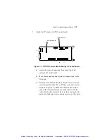
J2
J1
J3
J4
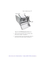
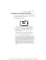
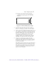
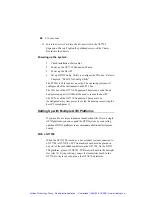
Figure 2-15: GTXI-701-PCR Bus Receiver Board
5. Set the line voltage of the GTXI unit to 110V or 220V as
needed. See “Selecting Line Voltage” earlier in this chapter.
6. Insert the GTXI-701-PCR Bus Receiver Board (Figure 2-15) in
the far right slot 13 on the platform. This board does not need
any special configuration. J1 is for the cable connection to the
GTXI-701-PCT Transmitter Board. J2 is used only when
connecting multiple GTXI platforms in a “daisy chain”
arrangement (contact Geotest technical support for further
information). J4 is for the local bus. J3 is for the ISA bus.
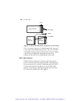
7. Using the 6-foot shielded cable provided with the Bus
Expansion Kit, connect the GTXI-701-PCT board in the host
PC to the GTXI-701-PCR board that is installed in slot 13 of
the GTXI system platform.
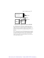
If the GTXI unit was ordered to be used in bus extender mode,
the GTXI-701-PCR board will be pre-installed by the factory.
If the GTXI was not ordered for use as a bus extender system,
the GTXI-701-PCR Bus Receiver Board must go in the far
right slot on the GTXI platform.
Artisan Technology Group - Quality Instrumentation ... Guaranteed | (888) 88-SOURCE | www.artisantg.com

