Chapter 3 - Installing Instrument Boards
73
On On
Off
Off
On
On
ADDRESS
MASK
OFFSET ADDRESS
BASE ADDRESS
ENABLE
DISABLE
SW2
SW1
0
1
Off
Off
Off Off
On
On
On
On On
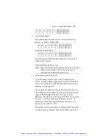
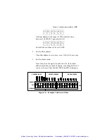
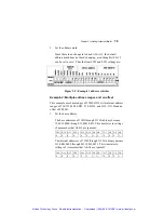
Figure 3-7: Example 3 address switches
Setting the GT7021 Carrier Board I/O Addressing
The GT7021 utilizes address lines A10-A15 for offset and A4-A9
for additional decoding. Address lines A4, A5 and A10-A12 can be
disabled in carrier addressing. The GT7021 has additional
addressing features like GTXI-702 compatible mode, Plug and
Play, and 16 bit addressing mode.
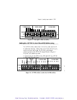
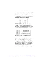
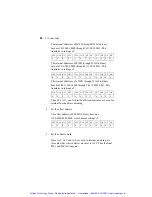
A typical setting for the DIP switches SW2 and SW1 for a GT7021
is given in the following figure:
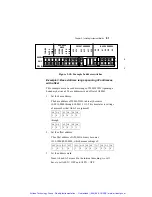
Figure 3-8: GT7021 address switches for 0x2300 address
On
ADDRESS
MASK
OFFSET ADDRESS
BASE ADDRESS
ENABLE
DISABLE
SW2
SW1
0
1
Off
On
On
On
Off
On
On
On
Off
On
A
4
A5
A6
A7
A8
A9
A1
0
A1
1
A1
2
A1
3
On
On
On
Off
Off
On
Off
Off
A1
4
A1
5
A4
EN
A5
EN
A1
0E
N
A1
1E
N
A1
2E
N
70
2E
N
Pn
PE
N
16
Bi
tE
N
0
1
Off
Artisan Technology Group - Quality Instrumentation ... Guaranteed | (888) 88-SOURCE | www.artisantg.com


