Chapter 3 - Installing Instrument Boards
87
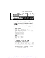
C B A
C B A
C B A
48
pins
Slot 5
Slot 6
Slot 7
Sub-bus
Sub-bus
Common Bus
1
2
16
J4
J4
J4
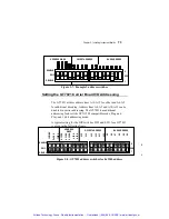
Figure 3-12:
Diagram of the J4 signals
on three adjacent boards
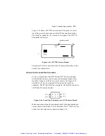
Connect to the Local Bus Connector
To use either a common bus or a sub-bus, first build and connect a
cable from each instrument board to the local bus connector of their
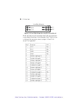
own carrier boards. See Figure 3-13 and Table 3-14 for a
description of the pins on the carrier’s local bus connector. The
local bus connector has 40 pins, 10 of which connect to the
common bus. These 10 lines are common to all ISA carrier boards,
but only six are common to PCI carrier boards. Twelve of these
connect ISA boards to the carrier board to the right on the GTXI
platform. Twelve others connect ISA boards to the board on the left.
The six remaining pins provide GND and VCC.
Artisan Technology Group - Quality Instrumentation ... Guaranteed | (888) 88-SOURCE | www.artisantg.com

