76
GTXI User's Guide
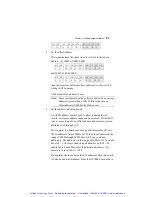
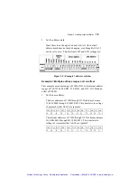
For example, 2A0H is 10,1010,0000. A3 through A0 are
ignored here, as indicated by the shading. This translates
into switch settings of:
A9 A8 A7 A6 A5 A4 A3 A2 A1 A0
1 0
1 0 1 0
0
0
0
0
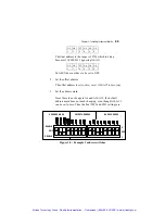
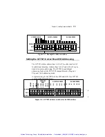
2. Set the offset address.
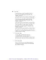
If two boards have the same value for A9-A4 in their base
address, say 300H (11,0000,0000)
A9 A8 A7 A6 A5 A4 A3 A2 A1 A0
1 1
0 0 0 0
0
0
0
0
and 308H (11,0000,1000),
A9 A8 A7 A6 A5 A4 A3 A2 A1 A0
1 1
0 0 0 0
1
0
0
0
then they must use different offset addresses, so their switch
settings will be unique.
The default offset address is zero.
Note:
Some instrument boards’ software drivers do not accept
addresses greater than 3FFH. If this is the case, an
offset address of 0000H should be used.
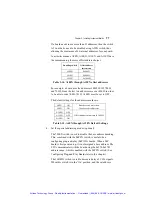
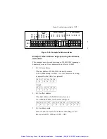
3. Set the address mask (optional).
An A4EN address mask is used to allow ignoring the A4
switch, so that a larger address range can be accessed. With
A4EN (on), every setting of one offset and base address uses
sixteen addresses (A0 through A3).
For example, if a board uses a range of addresses for I/O, say
the 20 addresses from 300H to 313H, then the addresses in the
range of 300H through 30FH have A4=0 (up to sixteen
addresses). The addresses in the range of 310H to 313H, would
have A4 = 1 (for more than sixteen addresses up to 32). To
enable A4 to be used for more than sixteen addresses, it is
necessary to turn A4EN = OFF.
Artisan Technology Group - Quality Instrumentation ... Guaranteed | (888) 88-SOURCE | www.artisantg.com


