


56
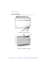
GTXI User's Guide
Setting ISA Carrier Board I/O Addressing
The GTXI system platform can perform I/O space addressing
beyond that which is normally done with standard PCs. Normal
decoding of PC I/O space utilizes address bits A0-A9, which
translate to address range 0x0000-0x03FF.
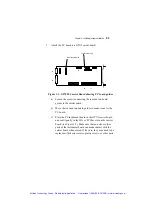
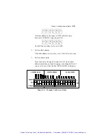
The ISA carrier boards have a bank of DIP switches that can add
offset addresses using address bits A10-A15 for the GT7020 and
GT7021, and A11-A15 for the GTXI-702, to any standard board
address. This offset is independent of the slot used by the carrier
board in the GTXI.
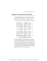
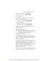
For example, if a PC board has a base address of 0x300, 0x1000 can
be added to get a new board address.
Board Base
Address
0x0300
(
note extra leading zero for alignment)
Offset Address
0x1000
New Base Address
0x1300
Table 3-2: Using Offset Address
Using this technique, up to 64 PC boards can be installed with the
same base address setting. However, some PC boards use some of
the A10 – A15 address lines for internal decoding, thus reducing the
number of boards that can use the same base address. For example,
a board with base address range 0x300-0x303 may use A10 for
internal decoding, thus occupying two address ranges: 0x300-0x303
and 0x700-0x703. If A11 is also used for internal decoding, then the
board occupies four address ranges: 0x300-0x303, 0x700-0x703,
0xB00-0xB03, and 0xF00-0xF03. Care should be taken when
setting an offset address to the carrier card that there is no conflict
with any address range used on other cards.
Artisan Technology Group - Quality Instrumentation ... Guaranteed | (888) 88-SOURCE | www.artisantg.com