82
GTXI User's Guide
Configuring Plug-and-Play Boards
When a plug-and-play (PnP) board is first powered up, it is not
assigned any resources. The CPU communicates with the board
using the 0x274-0x27B address range. After the PnP process has
completed, the CPU issues the same resources every time, unless
some PnP boards were removed or installed. To configure a carrier
with a PnP board, follow the following steps.
1. Set all the address switches of carrier(s) with PnP boards to ON
except SW2-1 (16BitEN).
2. Insert carrier(s) into GTXI chassis and reboot the CPU.
3. When the computer is done rebooting, write down the
resources assigned to the PnP board(s).
4. Turn off the power and set the carrier(s) according to the
assigned resources. Set the base address switches according to
the base I/O address assigned, MemS jumpers according to
memory address assigned (if any), and DACK jumper
according to DMA channel assigned (if any).
Setting ISA Carrier Board DMA Select
For some ISA carrier boards, DMA resources need to be allocated
prior to operating the GTXI. Check the manual for the instrument
board to see if it uses DMA channels. If it does:
1. Determine the DMA channels without conflicts.
2. Put the DMA acknowledge (DACK1 through DACK7)
jumpers on the appropriate DMA channel(s) on the carrier
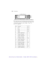
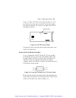
board as described in the instrument board manual. See Figure
3-1 for the location of the DMA Select on the top of the carrier
board. For example, if the instrument uses DMA #1, jumper
DACK1 should be installed. Several DMA channels can be
used in the same carrier. If the instrument’s DMA number does
not match the selection made on the carrier board, the
instrument’s DMA will not function.
Artisan Technology Group - Quality Instrumentation ... Guaranteed | (888) 88-SOURCE | www.artisantg.com


