Chapter 3 - Installing Instrument Boards
93
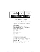
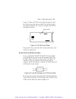
Figure 3-15 shows a GT7720 carrier board. The pins at J1 on the
rear of the carrier board connect to the PCI bus and the local bus.
The local bus connector, P1, consists of six signals. The GT7730
has similar connectors.
Figure 3-15: GT7720 Carrier Board
The pins in J1 allow a carrier board to be connected to other carrier
boards via a common bus.
Connect to the Local Bus Connector
To use a common bus with GT7720 and GT7730 carrier boards,
first build and connect a cable from each instrument board to the
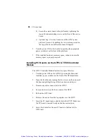
local bus Connector of their own carrier boards. See Figure 3-16
and Table 3-18 for a description of the pins on the local bus
connector. The PCI local bus has six signals, all of which connect to
all PCI and ISA carrier boards.
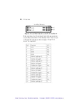
Figure 3-16: Local Bus Connector on a PCI Carrier Board
Make connections from the instrument board to the appropriate pin-
outs as shown in the Table 3-18. In this table, “Pin #” refers to a pin
on the local bus connector as shown in Figure 3-16.
Artisan Technology Group - Quality Instrumentation ... Guaranteed | (888) 88-SOURCE | www.artisantg.com

