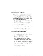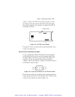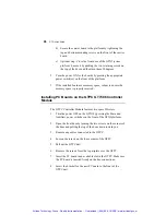
Chapter 3 - Installing Instrument Boards
91
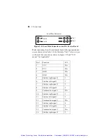
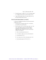
3. In a similar manner, use Table 3-14, go to “sub-bus right signal
9” to determine Pin 28 must be used for the board in slot 5.
4. Connect the instrument board on the carrier board in slot 5 to
the Pin 28 on the local bus connector.
Connecting Non-Adjacent Boards via a Sub-bus
To connect to a board that is not adjacent to that carrier board, for
example, slot 7 to slot 5:
1. First connect the instrument board in slot 7 to its local bus
connector Pin 29 as explained above.
2. Since the board in slot 6 is in between the boards in slot 7 and
slot 5, place a jumper on JP9 for slot 6. The JP number
corresponds to the sub-bus number in Table 3-14 and is
independent of the slot number. In that way, the signal goes
through the following path:
a) from the first instrument board in slot 7,
b) to its local bus connector on its carrier board to Pin 29,
c) to the signal in slot 7-C-9,
d) over on the sub-bus to slot 6 to the signal in slot 6-A-9,
e) then through the jumper at JP9 to slot 6-C-9,
Artisan Technology Group - Quality Instrumentation ... Guaranteed | (888) 88-SOURCE | www.artisantg.com

