84
GTXI User's Guide
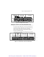
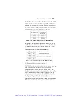
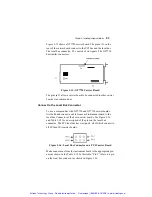
Set the MEM Select on the carrier board:
1. For
pre-defined
memory:
a) Put jumpers on the appropriate MEM pins on the carrier
board according to the desired address range.
b) If any instrument board in the GTXI uses MEM, make sure
that MEM signals are enabled on the DIP switch on the
buffer board (if the GTXI-700 is used for stand-alone
mode) or the GTXI-701-PCT board (if the GTXI is used
for bus extender mode). For further information, see
“Installing the GTXI platform for bus extender mode”
in
Chapter 2
. The default setting is to have MEM enabled.
c) In the GTXI-Config program, select the appropriate MEM
addresses. See
Chapter 4 “Assigning Resources”
for
further details.
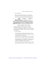
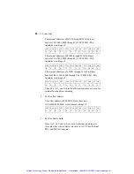
2. User-defined
memory:
a) Determine the necessary resources to the nearest 64k
address range.
b) Put the appropriate jumper on the MEMS0. MEMS1 is
reserved for future variations.
c) Make sure that MEM signals are enabled on the DIP
switch on the buffer board (if using the GTXI for stand-
alone mode) or the GTXI-701-PCT Transmitter Board (if
using the GTXI for bus extender mode). For more
information, see
“Installing the GTXI platform for bus
extender mode”
in
Chapter 2
.
The default setting is to
have MEM enabled.
d) In the GTXI-Config program, input the desired range
under ‘user-defined’ memory. See
Chapter 4 “Assigning
Resources”
for further details.
Artisan Technology Group - Quality Instrumentation ... Guaranteed | (888) 88-SOURCE | www.artisantg.com


