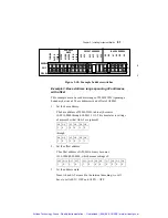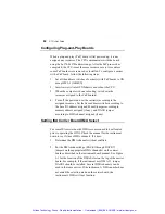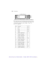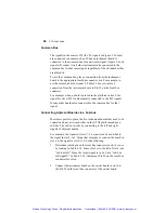
86
GTXI User's Guide
where the x=e000-ec00 is the range of memory to use on the
instrument. (Note that the normal convention for writing these
addresses leaves off one hex digit.) The x= command shown above
would exclude E0000 - EC000 from being used by other
applications.
Using the Local Bus with ISA Carrier Board
The GTXI has a built-in local bus enabling boards to communicate
and share signals. There are instances where two instrument boards
need to share signals. To do this, a connection must be made from
each board to its local bus.
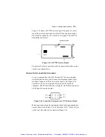
Local Bus Connector
Local Bus Jumpers
J2
J1
J3
J4
J5
Figure 3-11: ISA Carrier Board
Figure 3-11shows an ISA carrier board. The pins at J4 on the rear of
the carrier board connect to the local bus, while pins at J3 connect
to the ISA Bus. The local bus consists of 48 pins in three rows of 16
pins each.
The pins in J4 allow a carrier board to be connected to other carrier
boards via a common bus and sub-buses. Figure 3-12 shows a
diagram of the J4 signals on three adjacent boards in slots 5 through
7 as viewed by looking inside the GTXI platform and toward the
rear of the platform.
Artisan Technology Group - Quality Instrumentation ... Guaranteed | (888) 88-SOURCE | www.artisantg.com


