Chapter 3 - Installing Instrument Boards
83
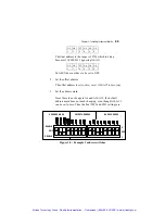
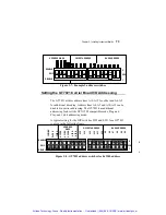
3. If any instrument board in the GTXI uses DMA, make sure that
DMA signals are enabled on the DIP switch on the buffer
board (if the GTXI-700 is used for stand-alone mode) or on the
GTXI-701-PCT board (if the GTXI is used for bus extender
mode). For more information, see
“Installing the GTXI
platform for bus extender mode.”
in
Chapter 2.
The default
setting is to have DMA enabled.
4. Assign the appropriate DMA channels in the GTXI-Config
program and save the changes. See
Chapter 4 “Assigning
Resources”
for further details.
Setting ISA Carrier Board Memory-Map Selection
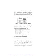
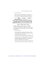
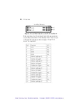
If the instrument board being used in the GTXI is memory-mapped
(i.e., it uses controller memory address space) then a memory-select
jumper on the ISA carrier board must be set. The memory select
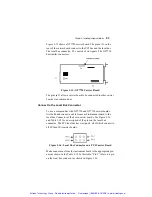
jumpers are located in a bank on the top of the carrier board, as
shown in Figure 3-1and Figure 3-2. They are labeled MEMS0
through MEMS5, with the MEMS5 jumper located in the right most
position.
The following table indicates the jumper settings for the desired
memory area:
Jumper Memory
MEMS0 User-defined
MEMS1 User-defined
MEMS2
D0000 - D7FFF
MEMS3
D8000 - DFFFF
MEMS4
E0000 - E7FFF
MEMS5
E8000 - EFFFF
Table 3-16: Carrier Board Memory Jumpers
Artisan Technology Group - Quality Instrumentation ... Guaranteed | (888) 88-SOURCE | www.artisantg.com

