


66
GTXI User's Guide
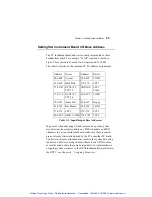
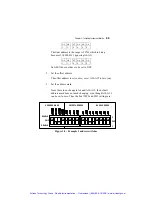
Setting the DIP Switches
The procedure for determining the DIP switch settings is explained
below. As a general rule note that no two carrier boards can have
the same combination of DIP switch settings.
1. Set the board base address:
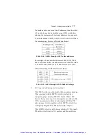
a) Start by converting the hexadecimal address into binary.
Hexadecimal Binary
1 0001
2 0010
3 0011
4 0100
5 0101
6 0110
7 0111
8 1000
9 1001
A 1010
B 1011
C 1100
D 1101
E 1110
F 1111
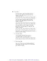
Table 3-9: Hexadecimal to binary conversion table
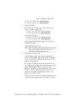
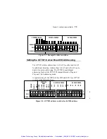
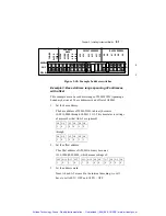
b) Use the binary value to set the switches (0 = on, 1 = off),
starting at A0 on the right and working toward A15 on the
left, using as many switches as necessary.
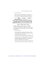
For example, 2A0H is 10,1010,0000. A3 through A0 are
ignored here, as indicated by the shading. This translates
into switch settings of:
Artisan Technology Group - Quality Instrumentation ... Guaranteed | (888) 88-SOURCE | www.artisantg.com