92
GTXI User's Guide
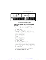
JP12
JP1
JP9
Figure 3-14: Carrier Board jumper across JP9
f) Which is automatically connected by sub-bus to slot 5-A-9
and the connection is finished.
Connecting Across a Gap of Several Boards
If a connection is to be made across a gap of several boards, for
example, from slot 10 to slot 5, jumpers must be placed on all the
boards between (for example, JP6 through JP9). That is, on slot 9,
slot 8, slot 7, and slot 6. The danger is if a board is removed in the
path, for example, slot 7, the connection is broken and now slot 10
is not connected to slot 5 anymore. The reason for the boards not
working as desired may not be realized.
To reduce the risk, try to place instrument boards that must connect
to each other in adjacent slots on the GTXI platform.
Using the Local Bus with a GT7720 and GT7730
Carrier Boards
The GTXI has a built-in local bus enabling boards to communicate
and share signals. There are instances where two instrument boards
need to share signals. To do this, a connection must be made from
each board to its local bus. The PCI local bus has six signals total,
all of which connect to all PCI and ISA boards.
Artisan Technology Group - Quality Instrumentation ... Guaranteed | (888) 88-SOURCE | www.artisantg.com


