Chapter 3 - Installing Instrument Boards
53
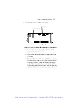
3. Attach the PC board to a GTXI carrier board:
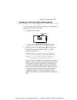
Top Board Guide
Rear Board Guide
J2
J1
J3
J4
J5
Figure 3-1: GT7020 Carrier Board showing PC board guides
a) Loosen the screws connecting the rear and top board
guides to the carrier board.
b) Move the rear and top board guides to make room for the
PC board.
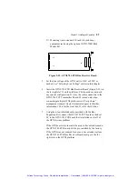
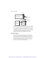
c) Place the PC instrument board in the GTXI carrier board
and seat it gently in the ISA or PCI bus slot on the carrier
board (see Figure 3-2). Make sure that no bolts or other
parts of the instrument board can make contact with the
carrier board when seated. If they are, they may need to be
replaced with shorter screws, plastic screws, or other parts.
Artisan Technology Group - Quality Instrumentation ... Guaranteed | (888) 88-SOURCE | www.artisantg.com

