Repair information
4-12
4447-20x
Go Back
Previous
Next
Disassembly
Flow chart
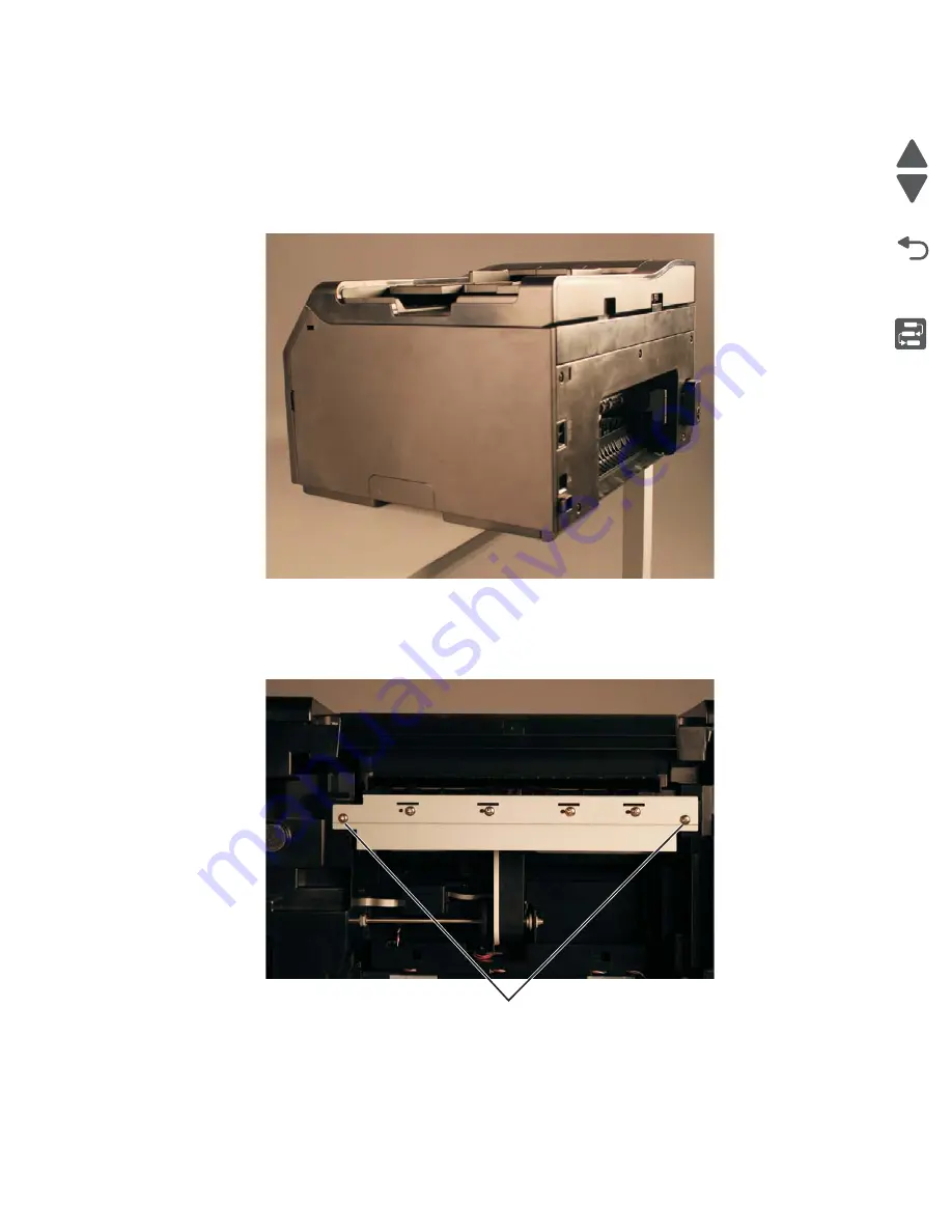
Wall rib housing removal
1.
Remove the input tray. See
“Input tray removal” on page 4-8
.
2.
Remove the duplex unit. See
“Duplex unit removal” on page 4-11
3.
Place the printer at the edge of the table.
4.
Remove the two screws (A) at the bottom of the printer.
Warning:
Be sure not to mar the surface of the printer.
A
Summary of Contents for Pro5500 Series
Page 11: ...Safety information xi 4447 20x Go Back Previous Next 012 3456789...
Page 254: ...4 85 Service Manual 4447 20x Go Back Previous Next Disassembly Flow chart...
Page 260: ...5 6 Service Manual 4447 20x Go Back Previous Next Wireless card Card reader JP3...
Page 261: ...Connector locations 5 7 4447 20x Go Back Previous Next Carrier card J1 J2 J3...
Page 262: ...5 8 Service Manual 4447 20x Go Back Previous Next...
Page 268: ...7 4 Service Manual 4447 20x Go Back Previous Next Assembly 2 Engine 1 2 3 5 4...
Page 270: ...7 6 Service Manual 4447 20x Go Back Previous Next Assembly 3 Fluid system assembly 1 3 2 5 4...
Page 274: ...7 10 Service Manual 4447 20x Go Back Previous Next...
Page 277: ...I 3 Service Manual 4447 20x Go Back Previous Next...


