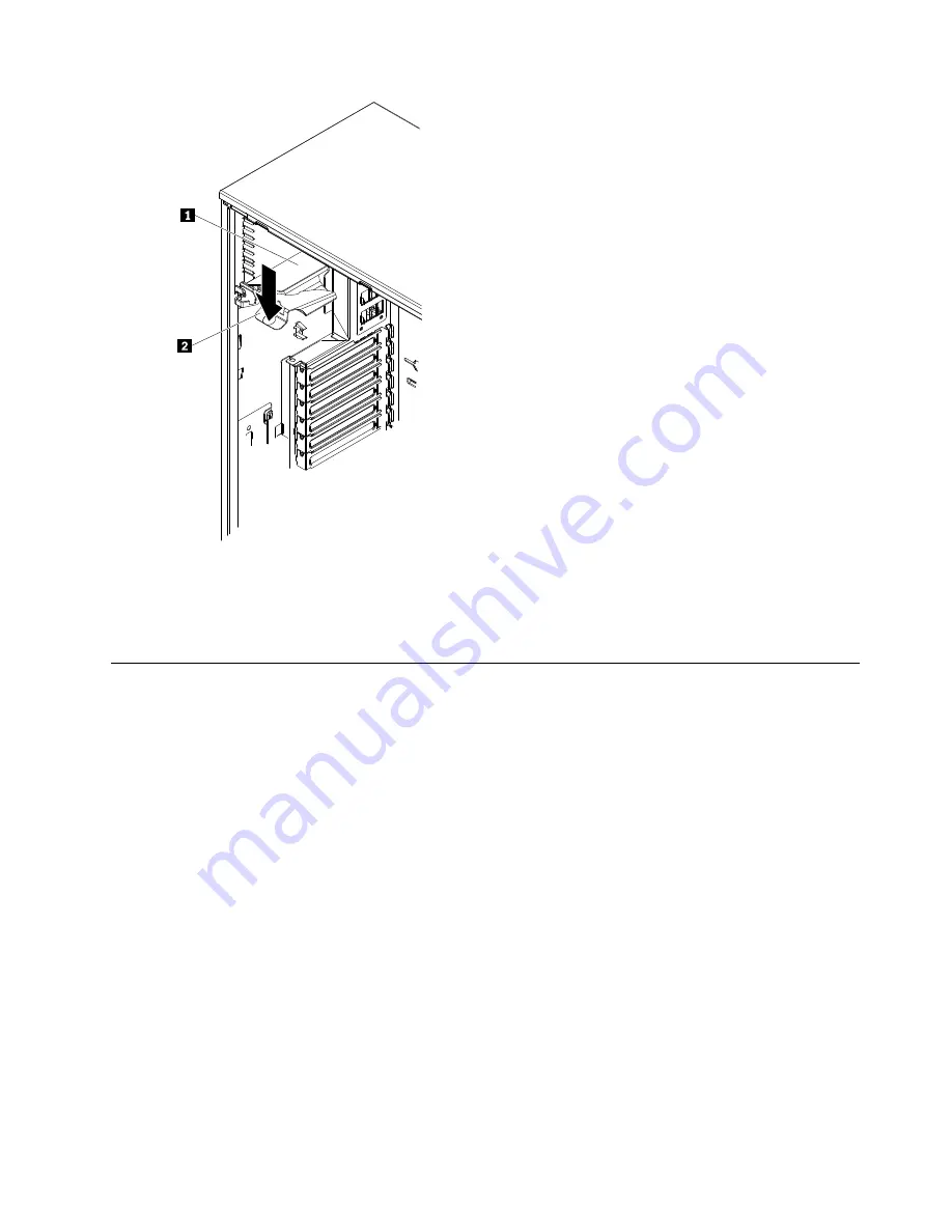
Step 7.
Install the side cover (see “Installing the side cover” on page 147).
Step 8.
Lock the side cover.
Step 9.
Reconnect the external cables and power cords; then, turn on the attached devices and turn on
the server.
Removing a microprocessor retention module
To remove a microprocessor retention module, complete the following steps:
Step 1.
Read the safety information that begins on page (see Chapter 2 “Safety information” on page 3).
Step 2.
Turn off the server and all attached devices; then, disconnect all power cords and external cables.
Step 3.
Carefully lay the server on its side so that it is lying flat and facing up.
Note:
Do not allow the server to fall over.
Step 4.
Unlock and remove the side cover (see “Removing the side cover” on page 146).
Step 5.
Rotate the power-supply cage assembly out of the chassis. Lift up the power-supply cage handle
and pull the power-supply cage assembly all the way up until the retainer latch locks the cage in
place on the chassis.
Chapter 7
.
Installing and replacing FRUs
199
Summary of Contents for ThinkServer TD200
Page 2: ......
Page 8: ...viii ThinkServer TD200 Hardware Maintenance Manual ...
Page 28: ...20 ThinkServer TD200 Hardware Maintenance Manual ...
Page 138: ...130 ThinkServer TD200 Hardware Maintenance Manual ...
Page 264: ...256 ThinkServer TD200 Hardware Maintenance Manual ...
Page 300: ...292 ThinkServer TD200 Hardware Maintenance Manual ...
Page 327: ...Lenovo product service Appendix A Getting help and technical assistance 319 ...
Page 328: ...320 ThinkServer TD200 Hardware Maintenance Manual ...
Page 338: ...330 ThinkServer TD200 Hardware Maintenance Manual ...
Page 344: ...336 ThinkServer TD200 Hardware Maintenance Manual ...
Page 345: ......
Page 346: ...Part Number Printed in USA 1P P N ...


