MAC III
5
Keysight 5500 SPM User’s Guide
5-10
First connect the 25 pin cable between the ASAB MAC III Aux
connector to the MAC/AACIII Aux Connector. This is shown as the red
line in
For the minimum configuration with no harmonics for KFM and EFM
FM modes, add one BNC cable between ASAB Lock-in 2 Input and the
MAC III or AAC III controller BNC2.
For the full configuration, designated by the yellow and blue lines in
on page 9, add a BNC “T” adapter to the MAC III or AAC
III controller BNC2 and connect two BNC cables:
1
to the ASAB Lock-in Amplifier 2 Input and
2
to the ASAB Lock-in Amplifier 3 Input.
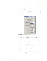
In PFM mode, Lock-in 2 drives the sample bias and monitors the
deflection signal to measure the amplitude of the cantilever motion
caused by the piezoelectric motion of the sample. This motion is very
small and often requires a very high gain before the lock-in (total Gain
x1024). The bias voltage applied between the tip and sample is usually
very large (20 Volts peak to peak) and the AC bias signal is routed
separately.
For PFM Mode, first connect the 25 pin cable between the ASAB MAC
III Aux connector to the MAC/AACIII Aux Connector. This is shown as
the red line in
Next connect a 6 foot BNC cable from ASAB Lock-in Amplifier 2
Drive Output to the sample plate connector adapter, as shown by the


